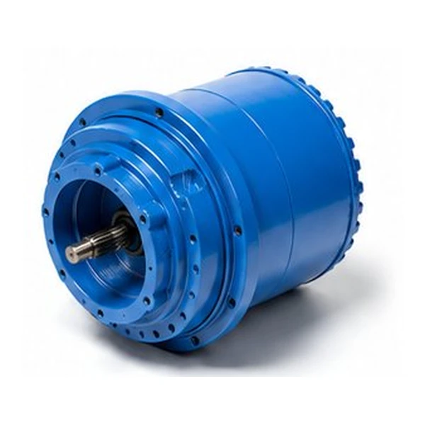
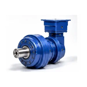
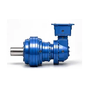
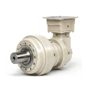
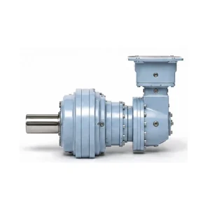
ZR03 Drejedrevet planetgearkasse — Retvinklet konisk planetgearkasse, 2-4 trin

EP-ZR03 — The First ZR Frame with 4-Stage Planetary Reduction
De EP-ZR03 is the transition point in the ZR slewing drive series where the architecture opens up from 2-3 stage reduction to a full 2-4 stage range. This fourth stage unlocks 25 additional high-ratio configurations (113.75-712.29) that the smaller ZR01 and ZR02 cannot reach, enabling ultra-low-speed slewing applications without oversizing to the heavier ZR06 frame.
At the 2-stage and 3-stage ratios, the ZR03 delivers 2,500 Nm continuous — exceeding the 2,100 Nm headline specification — with 5,300 Nm peak capacity for transient overloads. This positions the ZR03 precisely between the compact ZR01/02 range (750-1,100 Nm) and the mid-range ZR06 (4,000-5,000 Nm), filling the torque gap that previously forced engineers to either undersise or oversise their slewing mechanism.
DIN 5-6
-40 til +80 grader C
3.500 omdr./min.

ZR03 Technical Parameters — 40 Ratio Configurations
Continuous torque at N2 x h = 100,000 hours. Torque de-rates progressively at higher ratios within each stage count. The 4-stage table spans four distinct torque tiers (2,500 / 2,000 / 1,500 / 1,300 Nm) as the internal gear mesh path lengthens.
2-Stage — ZR03**2 (5 Ratios)
| Forhold | Kontinuerligt drejningsmoment (Nm) | Maks. drejningsmoment (Nm) | Maks. omdrejninger pr. minut | Pt F/M (kW) |
|---|---|---|---|---|
| 7.96 | 2,500 | 5,300 | 3,500 | 9.5 / 11.0 |
| 9.39 | 2,500 | 5,300 | 3,500 | 9.5 / 11.0 |
| 11.78 | 2,500 | 5,300 | 3,500 | 9.5 / 11.0 |
| 13.70 | 2,500 | 5,300 | 3,500 | 9.5 / 11.0 |
| 16.58 | 2,000 | 4,400 | 3,500 | 9.5 / 11.0 |
3-Stage — ZR03**3 (10 Ratios)
| Forhold | Kontinuerligt drejningsmoment (Nm) | Maks. drejningsmoment (Nm) | Maks. omdrejninger pr. minut | Pt F/M (kW) |
|---|---|---|---|---|
| 27.69 | 2,500 | 5,300 | 3,500 | 6.5 / 8.0 |
| 33.89 | 2,500 | 5,300 | 3,500 | 6.5 / 8.0 |
| 40.99 | 2,500 | 5,300 | 3,500 | 6.5 / 8.0 |
| 47.68 | 2,500 | 5,300 | 3,500 | 6.5 / 8.0 |
| 57.36 | 2,500 | 5,300 | 3,500 | 6.5 / 8.0 |
| 67.97 | 2,500 | 5,300 | 3,500 | 6.5 / 8.0 |
| 79.06 | 2,500 | 5,300 | 3,500 | 6.5 / 8.0 |
| 95.64 | 2,000 | 4,400 | 3,500 | 6.5 / 8.0 |
| 98.79 | 2,000 | 4,400 | 3,500 | 6.5 / 8.0 |
| 119.51 | 1,500 | 3,300 | 3,500 | 6.5 / 8.0 |
4-Stage — ZR03**4 (25 Ratios)
Torque de-rates in four tiers as ratio increases: 2,500 → 2,000 → 1,500 → 1,300 Nm continuous.
| Forhold | Kontinuerligt drejningsmoment (Nm) | Maks. drejningsmoment (Nm) | Maks. omdrejninger pr. minut | Pt F/M (kW) |
|---|---|---|---|---|
| 113.75 | 2,500 | 5,300 | 3,500 | 5.5 / 6.5 |
| 139.24 | 2,500 | 5,300 | 3,500 | 5.5 / 6.5 |
| 144.38 | 2,500 | 5,300 | 3,500 | 5.5 / 6.5 |
| 159.75 – 330.98 | 2,500 | 5,300 | 3,500 | 5.5 / 6.5 |
| 343.79 – 415.88 | 2,000 | 4,400 | 3,500 | 5.5 / 6.5 |
| 456.18 – 551.83 | 1,500 | 3,300 | 3,500 | 5.5 / 6.5 |
| 570.00 – 712.29 | 1,300 | 2,900 | 3,500 | 5.5 / 6.5 |
25 individual ratios within the 4-stage table. Full per-ratio data sheet available on request. Ratios 159.75 to 330.98 span 10 discrete values; 343.79 to 415.88 span 4; 456.18 to 551.83 span 4; 570.00 to 712.29 span 4.
Electric Motor Sizing — How to Match a Motor to the ZR03
While the ZR03 accepts both hydraulic and electric motor inputs, electric drive configurations (IEC induction motors with VFD control) are the most common in the 2,000-2,500 Nm application class. The following approach covers motor sizing for continuous-duty slewing applications.
Calculate Required Motor Power
Motor power (kW) = Output torque (Nm) x Output speed (rpm) / (9,550 x Gearbox efficiency). For a ZR03 at ratio 47.68 delivering 2,500 Nm at 30 rpm output: P = 2,500 x 30 / (9,550 x 0.91) = 8.6 kW. Round up to the next standard IEC motor frame: 11 kW (IEC 132M for 4-pole). Always verify that the calculated motor power does not exceed the thermal power rating (Pt) for the selected stage count.
Verify Thermal Compatibility
The effective continuous input power must not exceed Pt. For the 3-stage ZR03, Pt(F) = 6.5 kW fan-cooled, Pt(M) = 8.0 kW natural convection. If the 8.6 kW calculated above exceeds these limits, either add a forced-cooling fan shroud (raises Pt by approximately 30%), reduce the duty cycle, or upsize to the ZR06 frame.
Configure the VFD
Set the VFD maximum frequency to correspond to 3,500 rpm motor shaft speed (the gearbox mechanical limit). For a 4-pole motor at 50 Hz (1,450 rpm base), this is approximately 120 Hz. Enable motor thermistor monitoring to protect against low-speed overheating below 25 Hz. For applications requiring precise positioning, use vector-control VFD mode with encoder feedback rather than V/f mode. Contact vores ingeniørteam for VFD parameter recommendations specific to your motor brand and model.
Applications That Fit the 2,000-2,500 Nm Envelope
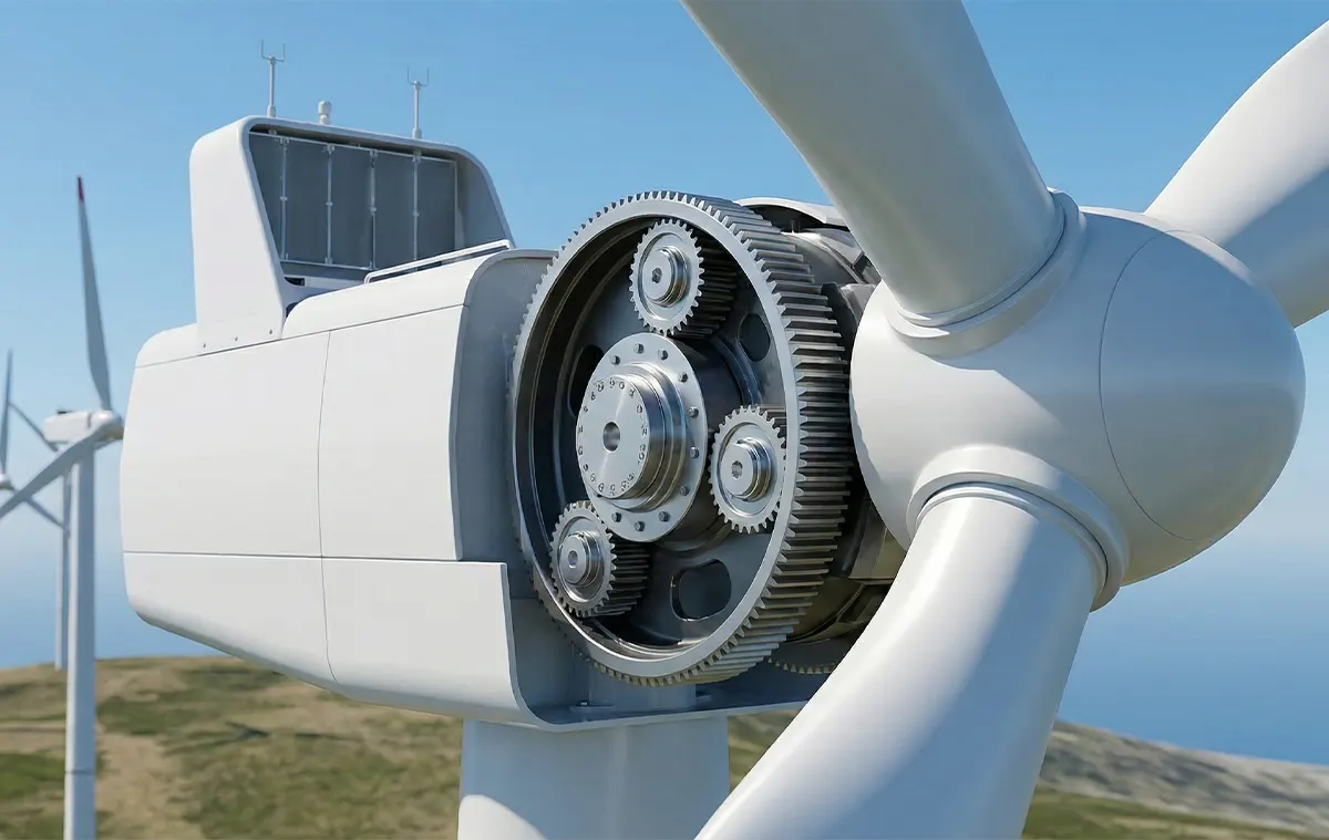
Wind Turbine Yaw Drives (Sub-1 MW)
Small and medium wind turbines with rotor diameters of 20-50 metres generate nacelle yaw torques of 1,200-2,400 Nm during normal wind-following operation. The ZR03 3-stage at ratios 40:1-68:1 provides the speed-torque combination these yaw mechanisms require, while the 5,300 Nm peak rating absorbs the storm-load transients that occur when the yaw brake releases against a cross-wind gust. Typical yaw systems use 2-4 ZR03 units equally spaced around the tower-top bearing.
Wastewater Treatment Rotary Distributors
Trickling filter rotary distributors and clarifier rake drive mechanisms rotate at 0.5-3 rpm under moderate radial and axial loads in permanently wet, chemically aggressive environments. The ZR03 4-stage at ratios 400:1-712:1 delivers the ultra-low output speed directly, eliminating the external chain or belt reduction stage typically required with single-stage drives. The IP67 sealed housing and FKM seals resist the hydrogen sulphide, chlorine, and UV exposure common in wastewater installations.
Robotic Base Rotation and Material Handling
Heavy-payload industrial manipulators and palletising robots with base rotation torques of 1,500-2,500 Nm use the ZR03 2-stage at low ratios (7.96-13.70) where fast, responsive rotation is critical for cycle time. The under-3-arcminute backlash enables repeatable angular positioning without external encoders in many automation scenarios, and the compact radial envelope integrates cleanly into the robot base pedestal without interfering with cable routing or service access.
Output Bearing Loads — What to Verify Before Committing to a Frame Size
The rated torque values in the specification table assume that the output bearing receives only torsional load through the pinion mesh. In real-world slewing applications, the output shaft also carries radial and axial forces from the pinion-to-slewing-ring engagement, wind loads on the structure being rotated, and payload imbalance. These external loads reduce the bearing L10 lifetime if not accounted for during the selection process.
The tangential force at the pinion-to-ring mesh generates a radial reaction on the output shaft bearing. This force equals the output torque divided by the pinion pitch circle radius. For a ZR03 at 2,500 Nm with a 50 mm pitch circle pinion, the radial force is 50 kN. Ensure this does not exceed the radial load rating published in the ZR03 technical drawing.
Helical slewing ring gears generate an axial thrust component proportional to the helix angle and the tangential mesh force. Straight-tooth (spur) slewing rings produce no axial thrust. If your slewing ring uses helical teeth, provide the helix angle and we will verify the axial load falls within the ZR03 output bearing capacity.
If the rotating mass is not symmetrically centred over the slewing ring (common in cranes and manipulators), the output shaft experiences a bending moment. This is the most commonly overlooked load in slewing drive selection. Provide the overhung mass, offset distance, and centre of gravity height, and we will include the moment load in the bearing life calculation.
The ZR03 output bearings are rated for an L10 life exceeding 20,000 hours under catalogue radial load conditions. If your combined load (radial + axial + moment) exceeds the catalogue assumptions, the L10 life decreases. We provide a free bearing life calculation report for every ZR03 order — submit your load data with the enquiry and the report ships with the quotation.
Every ZR03 output bearing pre-loaded and load-tested at the factory
Relaterede produkter

Ofte stillede spørgsmål
Kundefeedback
We maintain 34 sub-MW turbines and have standardised the ZR03**3 at ratio 57.36 for yaw drive replacements. The units have been performing reliably across 3 winter seasons, including sustained -28 deg C operation with the VG 150 oil specification. Previously we used a European brand that was triple the cost with comparable field life. Delivery to our site in northern Germany was 4 weeks on the last batch.
Rotary distributor drive at a wastewater treatment plant. Replaced a chain-driven worm reducer arrangement that needed re-tensioning every three months and threw grease everywhere. The ZR03 4-stage eliminated both the chain and the external reduction stage entirely. Clean installation, no maintenance in 14 months other than the scheduled oil change. The seals are holding up well in an H2S-rich environment.
Robot base drive for a palletising cell, ZR03**2 at 9.39 ratio. The backlash is within spec and the positioning repeatability is acceptable for our application. Solid mechanical quality. The 4-star rating is because the CAD model provided was a simplified envelope rather than a detailed model with bolt hole positions and shaft tolerances. We needed to request the detailed version separately, which added a few days to our design timeline.
Yderligere information
| Redaktør | Cxm |
|---|
Relaterede produkter
-

ZR35 Drejedrevet planetgearkasse — Retvinklet konisk planetgearkasse, 3-5 trin
-
ZR19 Drejedrevet planetgearkasse — Retvinklet konisk planetgearkasse, 2-5 trin
-
ZR16 Slewing Drive Planetary Gearbox — Right-Angle Bevel-Planetary, 2-5 Stage
-
ZR07 Slewing Drive Planetary Gearbox — Right-Angle Bevel-Planetary, 2-4 Stage
-
ZR02 Drejedrevet planetgearkasse — Retvinklet konisk planetgearkasse, 2-3 trin
-
ZR24 Slewing Drive Planetary Gearbox — Right-Angle Bevel-Planetary, 2-5 Stage
-
ZR06 Drejedrevet planetgearkasse — Retvinklet konisk planetgearkasse, 2-4 trin
-
ZR01 Drejedrevet planetgearkasse — Retvinklet konisk planetgearkasse


