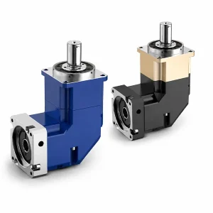
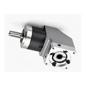
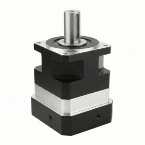
EP-TMR 정밀 직각 헬리컬 유성 기어박스

EP-TMR은 연마된 나선형 베벨 기어 단계를 추가합니다. EP-TM 유성 기어 코어를 사용하여 출력을 90° 회전시키면서 헬리컬 유성 기어의 토크 밀도와 저소음을 유지합니다. 모터 입력 방향은 좌, 우, 상, 하의 네 방향으로 조절 가능하여 기계 레이아웃에 따라 모터를 원하는 위치에 배치할 수 있습니다. 단점으로는 동일 프레임에서 EP-TM 대비 백래시가 +3 arcmin 증가하고 효율이 -2% 증가한다는 점입니다.
EP-TMR 시리즈 — 직각 헬리컬 유성 기어박스 | 프레임 크기 042–220 mm, P1/P2, i=3–200, 출력 90°
서보 모터와 부하 사이에서 기계 축이 90° 회전해야 할 때, 기존 방식은 외부 직각 베벨 기어박스 또는 표준 기어박스에 볼트로 고정된 웜 감속기를 사용하는 것입니다. 두 방식 모두 추가 부품, 추가적인 백래시 발생 원인 및 효율 손실을 초래합니다. EP-TMR 이 제품은 90° 스파이럴 베벨 회전 기어와 헬리컬 유성 기어 감속 장치를 하나의 밀폐형 하우징에 통합했습니다. 7가지 프레임 크기(0.42~220mm)로 17N·m에서 2,000N·m까지의 출력 토크를 제공하며, 기어비는 i=3에서 i=200까지, 단일 및 이중 스테이지 구성으로 제공됩니다. 모터 입력 방향(좌, 우, 상, 하)은 제조 시 고정되므로 주문 시 정확한 방향을 지정해야 합니다.
직각 헬리컬 유성 기어박스 · 스파이럴 베벨 90° 방향 전환 · 범용 서보 모터 어댑터 · 한국 창고 재고 보유
EP-TMR 시리즈 - 전체 성능 사양
모든 값은 주변 온도 20°C, 정격 부하, 그리스 윤활 조건에서 측정되었습니다. 베벨 기어 단 효율 손실은 동일한 정격 조건에서 EP-TMR과 EP-TM 간의 2~3% 차이를 설명합니다.
| 매개변수 | 단위 | 단계 | 티므르042 | 티므르060 | 티므르090 | 티므르115 | 티므르142 | 티므르180 | 티므르220 |
|---|---|---|---|---|---|---|---|---|---|
| 정격 출력 토크 T₂ₙ | 뉴엠 | L1 (i=3–20) | 17~22세 | 40~60세 | 130~160 | 208–330 | 342–650 | 588–1,200 | 1,140~2,000 |
| 뉴엠 | L2 (i=12–200) | 17~22세 | 40~60세 | 130~160 | 208–330 | 342–650 | 588–1,200 | 1,140~2,000 | |
| 최대 출력 토크 T₂max | 뉴엠 | L1/L2 | 3 × T₂ₙ (3배 정격) | ||||||
| 정격 입력 속도 nₙ | 회전수 | L1/L2 | 5,000 | 5,000 | 4,000 | 4,000 | 3,000 | 3,000 | 2,000 |
| 최대 입력 속도 n₁max | 회전수 | L1/L2 | 10,000 | 10,000 | 8,000 | 8,000 | 6,000 | 6,000 | 4,000 |
| 정밀 백래시 P1 | 아크민 | L1 (i=3–20) | ≤ 6 아크분 | ||||||
| 표준 백래시 P2 | 아크민 | L1 / L2 | 8아크민(L1) / 12아크민(L2) | ||||||
| 비틀림 강성 | N·m/arcmin | L1 | 3 | 7 | 14 | 25 | 50 | 145 | 225 |
| 허용 반경 방향 힘 Fr_max ¹ | N | L1/L2 | 780 | 1,530 | 3,300 | 6,400 | 9,400 | 14,500 | 50,000 |
| 허용 축력 Fa_max | N | L1/L2 | 350 | 765 | 1,625 | 3,200 | 4,700 | 7,250 | 25,000 |
| 전송 효율 η | % | L1 / L2 | ≥ 95%(L1) / ≥ 92%(L2) | ||||||
| 무게 (대략) | kg | L1 | 0.9 | 2.1 | 6.4 | 13 | 24.5 | 51 | 83 |
| 소음 (n=3,000 rpm, 무부하) | dB(A) | L1/L2 | ≤61 | ≤63 | ≤65 | ≤68 | ≤70 | ≤72 | ≤74 |
| 서비스 수명 | 시간 | L1/L2 | 20,000시간(연속) · 10,000시간(EP-TMR 정격 사양)* | ||||||
¹ 허용 반경 방향 하중은 축 중심(x = L/2)에 적용됩니다. 하중이 중심에서 벗어나 작용하는 경우, 위치 하중 계수표에서 돌출 위치 계수 Kb를 적용하십시오. 전체 계산 방법은 반경 방향 하중 계산 가이드 →를 참조하십시오. *연속 작동 시 베벨 단계 수명 등급.
-10°C ~ +90°C
IP65 표준
입력축에 대해 90°
밀봉 그리스 - 평생 보증
모든 방향
S1 라운드 / S2 키드
사용 가능한 기어비 및 주요 본체 치수
| 단계 | 사용 가능한 비율 | 능률 | 백래시 P1 | 일반적인 적용 사례 |
|---|---|---|---|---|
| L1 싱글 | 3 · 4 · 5 · 6 · 7 · 8 · 10 · 14 · 20 | ≥95% | ≤6′ | 포장 접힘 축, CNC 이송, 컨베이어 측면 구동 |
| L2 듀얼 | 12 · 15 · 20 · 25 · 30 · 35 · 40 · 50 · 60 · 70 · 80 · 100 · 120 · 140 · 160 · 200 | ≥92% | ≤10′ | 로봇 관절, 고비율 구동 장치, 공간 제약형 설치 |
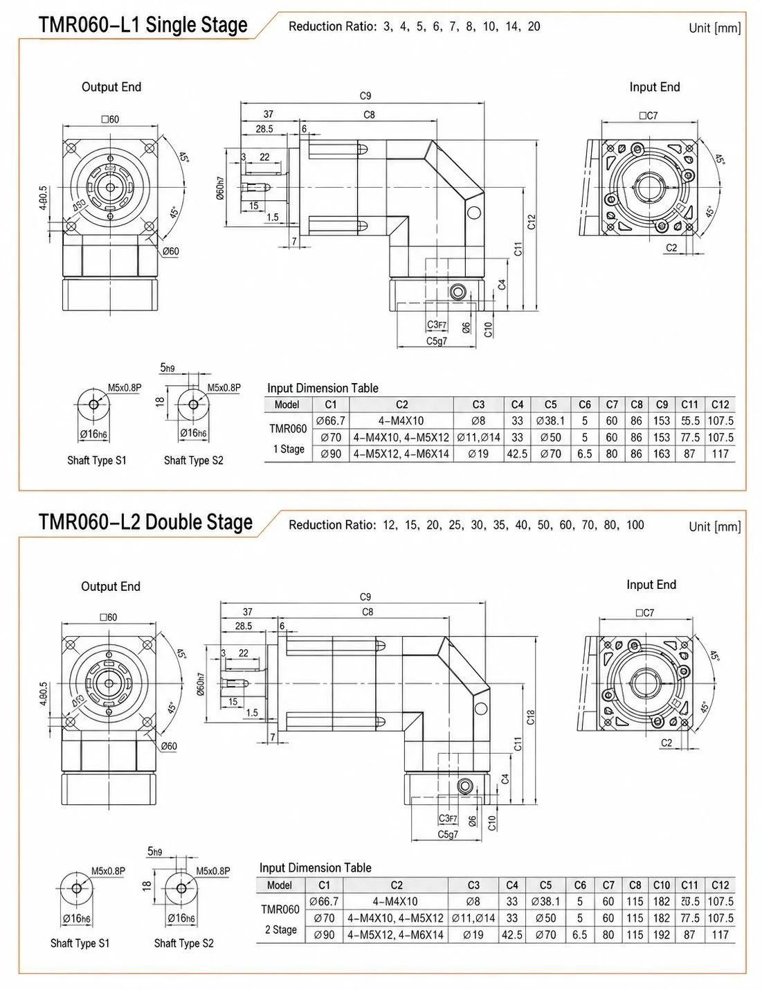
EP-TMR 키 본체 치수 — 단일 스테이지 L1
| 액자 | 출력면(정사각형) | 출력축 직경 | 전체 길이(L1) | 모터 페이스(사각형) | 입력 파일럿 Ø (C1) | 입력 볼트 원(C2) | 입력축 Ø (C3) |
|---|---|---|---|---|---|---|---|
| 티므르042 | □42 | Ø35h7 / Ø30g7 | 109mm | □42 | Ø46 | 4-M4×10 | Ø13 |
| 티므르060 | □60 | Ø80 플랜지 | 약 153mm | □60 (C7) | Ø66.7 / Ø70 / Ø90 | 4-M4 / M5 / M6 | Ø8 / Ø11 / Ø19 |
| 티므르090 | □90 | Ø116 플랜지 | 약 209mm | □90 (C7) | Ø90 / Ø100 / Ø115 / Ø145 | M5×12 – M8×20 | Ø19 / Ø16 / Ø19,22 |
| 티므르115 | □115 | Ø152 플랜지 | 약 267.5mm | □115 (C7) | Ø145 / Ø200 | 4-M8×20 / 4-M12×28 | Ø19,22 / Ø35 |
| 티므르142 | □142 | Ø186 플랜지 | 약 338mm | □142 (C7) | Ø145 / Ø200 | 4-M8×20 / 4-M12×28 | Ø22 / Ø35 |
| 티므르180 | □180 | Ø160h7 / Ø114.3 | 약 394mm | □180 | 관습 | 4-M12×30 | 관습 |
| 티므르220 | □220 | Ø180h7 / Ø114.3 | 약 484mm | □180 (C7) | 관습 | 4-M12×30 | 관습 |
TMR180 및 TMR220의 입력 치수는 고객 맞춤형으로 제공됩니다. 주문 시 모터 모델 번호를 명시해 주십시오. 기계 설계를 최종 확정하기 전에 모든 치수를 한국 에버파워(Korea Ever-Power)의 치수 도면과 대조하여 확인하십시오.
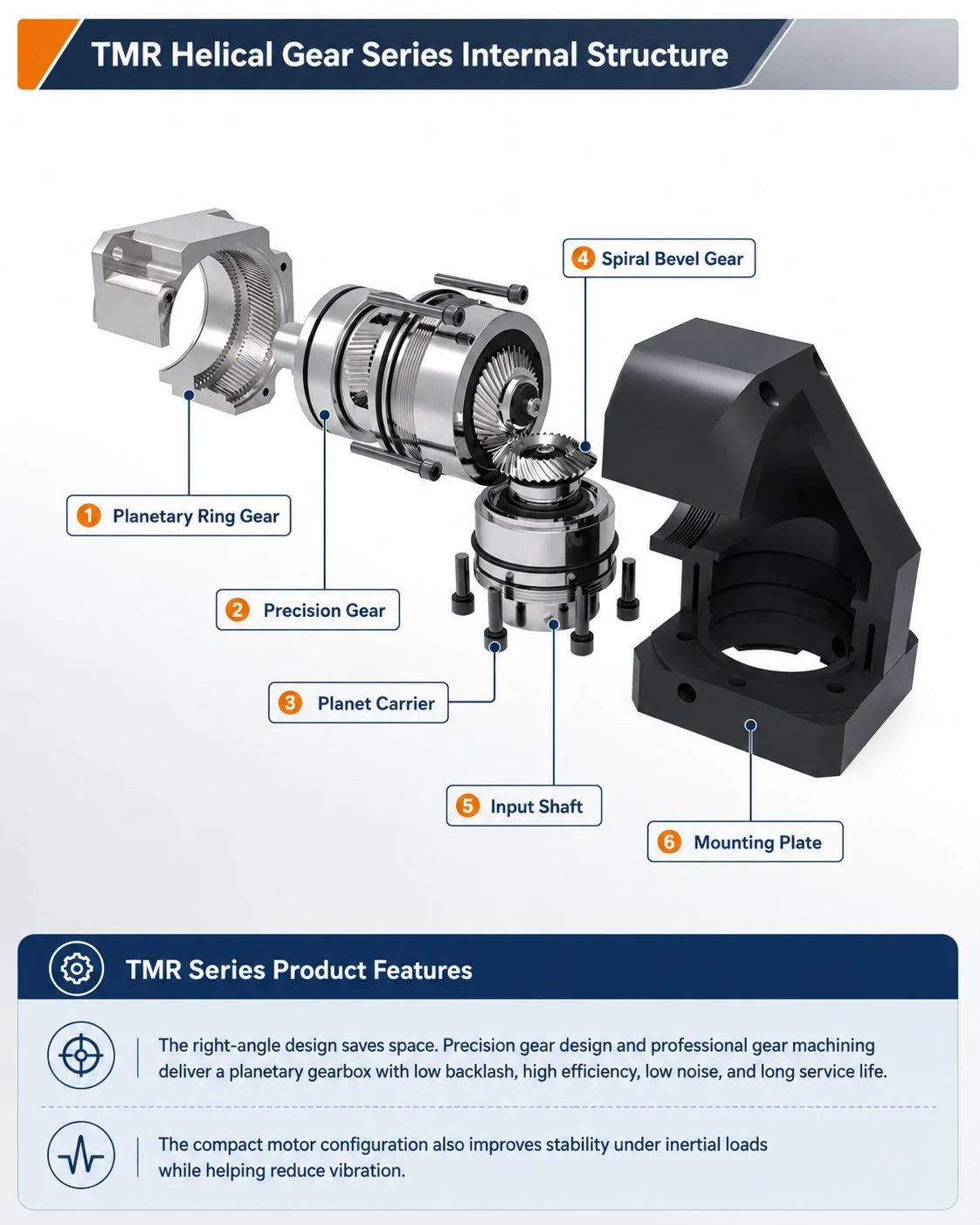
EP-TMR을 컴팩트한 직각 솔루션으로 만들어주는 6가지 엔지니어링 이점
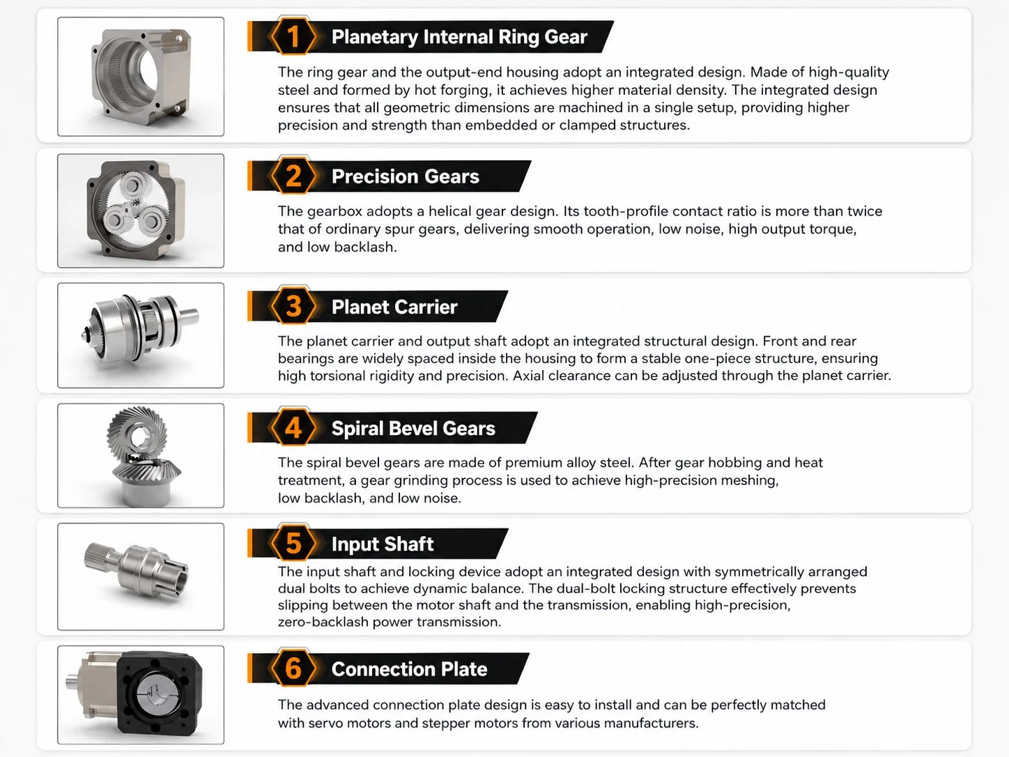
표준 유성 기어박스에 직각 베벨 감속기를 추가하면 두 번째 하우징, 두 번째 베어링 시스템, 두 번째 윤활 요구 사항 및 두 번째 백래시 발생 원인이 생깁니다. EP-TMR은 헬리컬 유성 감속기와 스파이럴 베벨 90° 회전을 하나의 단조 합금 하우징에 통합하고 하나의 밀봉된 그리스 주입구만 사용합니다. 조립된 장치는 동일한 토크 정격에서 두 개의 하우징으로 구성된 솔루션보다 길이가 짧고 가벼우며 마모 부품 수가 적습니다.
베벨 기어단은 직선 베벨 기어가 아닌 25~35°의 헬릭스 각도와 58~62 HRC의 표면 경도를 가진 연삭 가공된 스파이럴 베벨 기어를 사용합니다. 스파이럴 베벨 접촉은 순간적인 충격이 아닌 치면을 따라 점진적으로 쓸어내리는 방식으로 이루어지므로, 동일한 치하중에서 직선 베벨 기어보다 베벨 기어단 소음이 4~6dB 낮습니다. EP-TMR의 3,000rpm에서의 소음은 프레임에 따라 61~74dB(A) 이하이며, 일반적으로 동일한 프레임의 EP-TM 인라인 기어보다 5dB 높습니다.
유성 기어 캐리어와 베벨 피니언 샤프트는 하나의 통합 부품으로 가공되어 유성 기어의 출력이 중간 커플링 없이 베벨 피니언으로 직접 전달됩니다. 이러한 커플링을 제거함으로써 조립 설계에서 캐리어와 피니언 연결부에 누적될 수 있는 런아웃을 없앨 수 있습니다. 베벨 기어 단의 소음과 백래시는 유성 기어 캐리어와 베벨 피니언 샤프트 사이에 별도의 커플링을 사용하는 경쟁사의 직각 기어 장치보다 낮습니다.
베벨 스테이지 하우징은 모터 입력 방향이 출력 샤프트에 대해 왼쪽, 오른쪽, 위쪽 또는 아래쪽으로 향하도록 지정할 수 있습니다. 이는 제조 시 베벨 하우징의 방향에 따라 설정되며 현장에서 변경할 수 없습니다. 이러한 유연성 덕분에 모터가 특정 방향으로 기계 프레임에서 나와야 하는 경우 발생하는 길이 증가, 정렬 오류 및 유지 보수 복잡성을 야기하는 맞춤형 샤프트 구성이 필요 없어집니다. 주문 시 모델 코드에 필요한 입력 방향(L, R, U 또는 D)을 지정하십시오.
EP-TMR 이중 스테이지는 EP-TM의 i=100 대비 i=200까지 도달합니다. 이러한 확장된 범위는 90° 방향 전환과 높은 기어비가 동시에 요구되는 직각 컨베이어 구동 장치, 선회 링 액추에이터, 저속 태양광 추적 장치 구동 장치에 특히 유용합니다. i=200에서 3,000rpm 모터는 출력을 15rpm으로 구동하는데, 이는 무거운 회전 테이블 위치 제어 및 웜 기어 예비 단계에 적합합니다. EP-TMR은 자체 잠금 웜 최종 단계 전에 고효율 1차 감속기를 추가합니다.
기존의 인라인 기어박스와 외부 직각 베벨 어댑터를 함께 사용하면 축 방향 길이가 두 장치를 직렬로 연결한 것과 같습니다. EP-TMR은 단일 하우징 설계로 길이가 더 짧습니다. 90° 회전부가 기어박스 내부에 있기 때문입니다. 기계 기둥, 로봇 관절 하우징, 컨베이어 측면 프레임과 같이 출력축 뒤쪽의 축 방향 깊이가 제한적인 경우, EP-TMR은 외부 베벨 어댑터의 길이만큼 전체 구동 어셈블리의 깊이를 줄여줍니다. 깊이를 줄이기 위해 모터를 측면으로 접어야 하는 설치의 경우, 해당 내용을 참조하십시오. EP-TNR 직각 플랜지 시리즈.
출력축 부하 엔지니어링 — TMR 장치와 인라인 장치의 결정적인 차이점
EP-TMR의 직각 출력축은 동일한 EP-TM 인라인 출력축보다 더 복잡한 하중 상태를 견뎌야 합니다. 이러한 복잡성 때문에 세심한 설계가 필요하며, 이것이 바로 동일한 프레임 크기에서 EP-TMR의 허용 반경 방향 하중 사양이 EP-TM의 값과 동일하지 않은 이유입니다.
경사면 가공 단계에서의 내부 예압: 정상 작동 시, 스파이럴 베벨 기어의 맞물림은 베벨 축에 분리력, 접선력 및 축력을 발생시킵니다. 이러한 내부 힘은 출력 축 끝에 가해지는 외부 하중과 관계없이 항상 존재합니다. EP-TMR 베어링 시스템은 이러한 내부 힘을 상쇄하는 예압식 앵귤러 콘택트 베어링으로 설계되었지만, 베어링 정격 용량의 일부를 소모합니다. 따라서 EP-TMR 출력 축에서 허용되는 외부 레이디얼 힘은 동일한 프레임의 EP-TM 출력 축에서 허용되는 외부 레이디얼 힘보다 약간 낮습니다.
돌출 위치 계수 K비: 외부 레이디얼 하중이 축 중심(x = L/2xL)에 가해질 때, 허용 가능한 최대 레이디얼 힘이 작용합니다. 하중이 베어링에서 멀어질수록(x가 L/2xL을 초과할수록), 출력축의 굽힘 모멘트는 증가하고 허용 가능한 레이디얼 힘은 위치 계수 K에 따라 감소합니다.비두 변수 간의 관계는 선형적이지 않습니다. 전체 차트 및 계산 방법은 한국 에버파워의 위치 부하 계수 차트 또는 방사형 부하 계산 가이드를 참조하십시오.
축하중 공식 — EP-TMR
F₂ᵣ_allowed = F₂ᵣ_perm (정격 값) F₂ᵣ가 중심에서 벗어나 작동할 때:
F₂ᵣ_허용값 = Kb × F₂ᵣ_권한
(위치 계수 차트의 Kb, Kb < 1) 결합된 방사형 + 축 방향 하중:
F₂ₐ ≤ 0.2 × F₂ᵣ_perm
F₂ₐ_max ≤ 0.1 × F₂ᵣ_perm
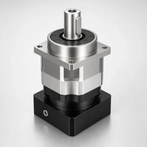
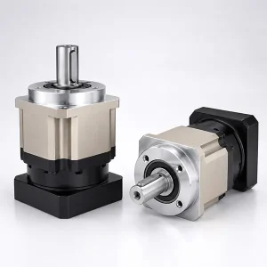
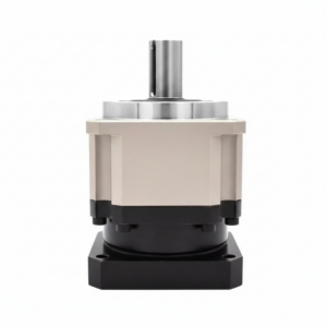
EP-TMR (본 페이지): 사각형 본체 하우징, EP-TM과 동일한 플랜지. 인라인 유닛 교체 또는 기계 프레임에 사각형 본체 기어박스 장착 방식이 사용되는 경우에 가장 적합합니다.
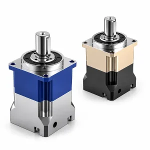
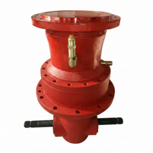
EP-TNR원형 플랜지 출력. 더 큰 직경의 출력 플랜지가 필요하거나, 출력 인터페이스에서 더 높은 모멘트 용량이 요구되거나, 로봇 플랜지에 직접 장착해야 하는 용도에 적합합니다.
한국 산업 현장에서의 EP-TMR - 직각 출력으로 실제 설계 문제를 해결하다
한국산 선반 및 터닝 센터의 툴 터릿은 스핀들 간섭을 피하기 위해 서보 모터를 터릿 회전축에 수직으로 배치해야 합니다. i=10–25의 EP-TMR060/090은 표준 구성으로, 모터는 측면에 장착되고 터릿은 출력축을 중심으로 회전합니다. 낮은 백래시(P1 ≤6 arcmin) 덕분에 추가적인 기준 센서 없이 엔코더 기반 위치 확인이 가능합니다.
한국 제약회사에서 사용하는 블리스터 포장 및 카톤 접지기는 EP-TMR을 이용하여 접지 암과 밀봉판을 구동합니다. 구동축은 기계 프레임 뒤쪽이나 옆쪽에 위치하며, 동작 방향과 일직선이 아닙니다. 90° 출력 덕분에 커플링 및 샤프트 연장 어셈블리가 필요 없어 접지 메커니즘의 누적 각도 오차가 줄어들고 기계 프레임 설계가 간소화됩니다.
메카넘 또는 옴니휠을 사용하는 한국의 전자상거래 물류 AGV는 수직으로 장착된 모터에서 구동력을 얻기 위해 휠 코너에 TMR042/060을 사용합니다. TMR042는 컴팩트한 크기(전체 길이 109mm, 단면적 □42 정사각형)로 표준 인라인 유닛이 장착될 수 없는 제한된 휠 코너 공간에 적합합니다. i=5–10의 단일 단계 기어비는 배터리 구동 AGV 작동에 적합한 높은 효율을 유지합니다.
한국 제조 공장의 전면 개방형 통합 포드 이송 로봇은 SEMI E84 풋프린트 표준을 준수해야 합니다. TMR060/090은 서보 모터를 로봇 베이스 플레이트와 평행하게 장착할 수 있어, 인라인 구성에 비해 모터 본체 길이만큼 로봇의 전면 깊이를 줄일 수 있습니다. 고정밀 P1 버전은 SEMI 표준 요구 사항인 ±1mm 이내의 FOUP 위치 정확도를 보장합니다.
한국의 식품 가공 라인(김치, 즉석식품, 포장 스낵)에서는 TMR090/115 모터를 사용하여 컨베이어 프레임 측벽에서 컨베이어 벨트 헤드 드럼을 구동합니다. 모터는 컨베이어 측면에 수직으로 장착되어 컨베이어 상단을 제품 이송에 방해되지 않도록 하며, 출력축은 드럼 축에 직접 연결됩니다. IP65 등급으로 식품 가공 환경에서도 세척이 가능합니다.
한국의 곡물 건조기, 화학 교반기, 콘크리트 혼합기 설비에서는 TMR115/142/180(i=25~100)을 사용하여 수직 모터로 수평 스크류 컨베이어를 구동합니다. 고비율 2단(i=100~200)은 표준 유도 모터로 매우 느린 스크류 컨베이어 속도(5~30rpm)를 구현할 수 있습니다. 이러한 고주기 저속 작동 환경에서 TMR의 밀폐형 그리스 구조는 동일한 구성의 웜 감속기에 필요한 오일 윤활 유지 보수를 없애줍니다.
EP-TMR 모델 코드 읽는 방법
헬리컬 유성 기어박스
042/060/090/115/142/180/220
L1: 3~20명 · L2: 12~200명
S1 = 원형 · S2 = 키형
P1 ≤6' · P2 ≤8'/≤12'
주문 시 모터 모델을 지정하십시오.
EP-TMR P1 규격의 ≤6 arcmin은 EP-TM P1 규격의 ≤3 arcmin보다 약간 넓습니다. 이는 품질 차이가 아니라, 베벨 스테이지 자체의 백래시가 전체 시스템 백래시에 더해진 것을 반영한 것입니다. 출력축에서는 두 규격 모두 동일한 표준 측정 방법을 사용하여 측정합니다(백래시 가이드 참조 →). 직각 구성임에도 불구하고 출력에서 ≤3 arcmin의 백래시가 요구되는 경우, EP-TMR P1 규격을 명시하십시오. EP-TNR 또는 TMR 초정밀 옵션에 대해서는 한국 에버파워에 문의하십시오.
자주 묻는 질문 — EP-TMR 시리즈
고객 리뷰 및 현장 성능
5 ★
87%
4 ★
11%
≤3 ★
2%
EP-TMR090 P1 i=20은 모터가 기계 프레임에서 측면으로 나와야 하는 측면 구동 컨베이어 헤드에 사용되었으며, 인라인 공간이 전혀 없었습니다. 기존 솔루션은 동일 위치에 직각 웜 감속기를 사용했는데, 효율이 70%에 불과했고 여름철 하우징 온도가 65°C까지 상승했습니다. EP-TMR090은 효율이 95% 이상으로 향상되어 정상 작동 시 하우징 온도가 43°C까지 떨어졌습니다. 또한 웜 감속기의 분기별 오일 교환 주기도 없어졌습니다. 3교대 근무 환경에서 18개월 동안 유지 보수가 한 번도 발생하지 않았습니다. 한국 에버파워는 당일 야스카와 SGMGV-09A에 맞는 모터 어댑터를 제공해 줄 것을 확인해 주었습니다.
EP-TMR115 P1 i=25는 수평 밀링 머신의 Z축에 사용되었는데, 서보 모터가 아래쪽이 아닌 기계 뒤쪽을 향해야 하는 경우였습니다. 90° 출력 덕분에 수직 방향으로 160mm의 여유 공간이 확보되어 Z축 이동 거리를 늘릴 수 있었습니다. 3,000rpm에서의 스파이럴 베벨 소음은 정격 소음 기준 68dB 이하로 매우 허용 가능한 수준이었습니다. 4가지 입력 방향 옵션 덕분에 맞춤형 샤프트 제작이 필요 없었습니다. 생산 라인에서 12개월 동안 사용해 본 결과, 백래시는 납품 증명서와 비교하여 변함이 없었습니다.
EP-TMR142 P2 i=40 듀얼 스테이지 기어박스는 고하중 스폿 용접 로봇의 베이스 회전(J1)에 사용됩니다. 90° 출력 덕분에 모터를 베이스 컬럼 내부에 수직으로 장착하여 후방으로 돌출되는 것을 방지하고 로봇의 바닥 설치 공간을 220mm 줄였습니다. 용접 건 클램핑 시 정격 토크의 3배(T₂max = 1,950 N·m)의 부하에서도 기어박스는 연간 36,000회 사이클 동안 측정 가능한 백래시 증가 없이 안정적으로 작동했습니다. 납품 인증서를 받았으며, 실제 측정값은 7.2 arcmin으로 P2 규격(≤10 arcmin)을 충분히 만족합니다.
EP-TMR 신청 경험을 공유해 주세요. 한국 에버파워에 문의하세요: [email protected]
EP-TMR 사양을 지정하세요 — 한국 Ever-Power 직각 전문 기술
한국 에버파워는 랙앤피니언 및 벨트 구동 직각 구성에 대한 레이디얼 하중 검증을 포함하여 모든 EP-TMR 적용 분야에 대해 프레임 크기, 기어비, 백래시 등급, 출력축 하중 및 모터 어댑터를 확인합니다. 한국어 지원, 당일 응답 서비스를 제공합니다.
직각 기어박스 적용 지원 · 당일 응답 · 한국 창고 재고 보유
추가 정보
| 편집자 | Cxm |
|---|
관련 상품
-
EP-AF 시리즈 고강성 출력축 인라인 유성 기어박스 (EP-AF042~EP-AF220 및 EP-AFX 변형)
-
BABR 시리즈 고정밀 유성 기어박스 - 원형 플랜지형 (EP-BABR042 ~ EP-BABR220)
-
BAB 시리즈 고정밀 유성 기어박스 - 표준 플랜지 (EP-BAB042 ~ EP-BAB220)
-
일반 산업용 표준 직각 유성 기어박스 — WPL 시리즈 (WPL40–WPL120)
-
일반 산업용 표준 경제형 유성 기어박스 — PL 시리즈 (PL40–PL160)
-
체인 구동식 사료 혼합기용 PGA 오거 유성 기어박스
-
정밀 유성 기어박스 | 산업용 PZB 시리즈
-
산업용 체인 구동 장치용 PLS 정밀 유성 기어박스


