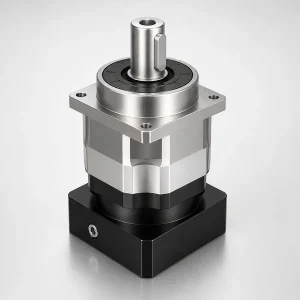
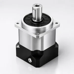
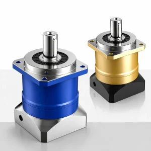
เกียร์ทดรอบแบบเฟืองดาวเคราะห์เกลียว EP-TNF หน้าแปลนกลม

เมื่อโหลดถูกยึดติดโดยตรงกับหน้าเอาต์พุตของเกียร์บ็อกซ์ เช่น ข้อต่อแขนหุ่นยนต์ โต๊ะหมุน CNC หรือดุมหัวแบ่งตำแหน่ง ไม่จำเป็นต้องใช้ข้อต่อ EP-TNF ขจัดความจำเป็นของข้อต่อโดยการจัดหาหน้าแปลนกลมที่มีความแม่นยำสูง (เส้นผ่านศูนย์กลาง 80–292 มม. เจียรให้มีความคลาดเคลื่อนไม่เกิน 0.02 มม.) ที่เชื่อมต่อโดยตรงกับโหลด ประสิทธิภาพเท่ากันกับ อีพี-ทีเอ็ม (≥97% L1) ระยะคลายตัว P1 กว้างขึ้นเล็กน้อย (≤5 arcmin เทียบกับ ≤3 arcmin) เนื่องมาจากรูปทรงของแบริ่งหน้าแปลน
เกียร์ทดรอบแบบเฟืองดาวเคราะห์เกลียว EP-TNF ซีรีส์ | เฟรม 060–220 มม., P1/P2, หน้าแปลน Ø80–292 มม.
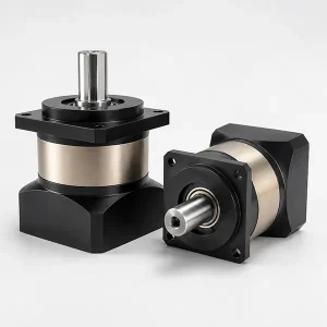
เดอะ เกียร์ทดรอบแบบเฟืองดาวเคราะห์เกลียวหน้าแปลนกลม EP-TNF ออกแบบมาสำหรับงานที่ส่วนต่อประสานโหลดเป็นวงกลมสลักเกลียว ไม่ใช่รูเพลา เช่น แขนหุ่นยนต์ที่ยึดติดกับหน้าเอาต์พุตของเกียร์บ็อกซ์ โต๊ะหมุน CNC ที่มีตัวกำหนดตำแหน่งนำร่องของตัวเรือนสำหรับยึดเกียร์บ็อกซ์ หัวแบ่งตำแหน่งแบบขับตรง — ทั้งหมดนี้ต้องการหน้าแปลนวงกลมสลักเกลียวที่เอาต์พุตของเกียร์บ็อกซ์ ไม่ใช่ปลายเพลาที่จะต้องเชื่อมต่อกับโหลด มีขนาดเฟรมหกขนาด (060–220 มม.) ครอบคลุมแรงบิดเอาต์พุตตั้งแต่ 50 N·m ถึง 2,000 N·m ด้วยอัตราส่วน i=3 ถึง i=100 มีระดับการคลายตัวสองระดับ — P1 (≤5 arcmin) และ P2 (≤7 arcmin) — ครอบคลุมการใช้งานเซอร์โวแบบกำหนดตำแหน่งและควบคุมความเร็วของเกาหลีตามลำดับ เฟรมขนาด 042 ไม่มีจำหน่ายใน TNF ขนาดขั้นต่ำคือ 060
เกียร์ทดรอบแบบเฟืองดาวเคราะห์ความแม่นยำสูงแบบหน้าแปลนกลม · อินเตอร์เฟซเชื่อมต่อโดยตรงกับแขนหุ่นยนต์/โต๊ะหมุน · อะแดปเตอร์สากล IEC/NEMA · สินค้าพร้อมส่งจากคลังสินค้าเกาหลี
ซีรี่ส์ EP-TNF — ข้อมูลจำเพาะด้านประสิทธิภาพโดยละเอียด
ค่าทั้งหมดวัดที่อุณหภูมิ 20°C, รับน้ำหนักตามพิกัด, และใช้จาระบีหล่อลื่นแบบปิดผนึก EP-TNF เริ่มต้นที่เฟรม 060 — ไม่มีเฟรม 042 ในซีรี่ส์ TNF
| พารามิเตอร์ | หน่วย | เวที | ทีเอ็นเอฟ060 | ทีเอ็นเอฟ090 | ทีเอ็นเอฟ115 | ทีเอ็นเอฟ142 | ทีเอ็นเอฟ180 | ทีเอ็นเอฟ220 |
|---|---|---|---|---|---|---|---|---|
| แรงบิดเอาต์พุตที่กำหนด T₂ₙ | เอ็น·ม | L1 (i=3–10) | 50–60 | 130–160 | 208–330 | 342–650 | 588–1,200 | 1,140–2,000 |
| L2 (i=12–100) | 50–60 | 130–160 | 208–330 | 342–650 | 588–1,200 | 1,140–2,000 | ||
| แรงบิดเอาต์พุตสูงสุด T₂max | เอ็น·ม | L1/L2 | 3 × T₂ₙ (3 เท่าของอัตรา) | |||||
| ความเร็วอินพุตที่กำหนด nₙ | รอบต่อนาที | L1/L2 | 5,000 | 4,000 | 4,000 | 3,000 | 3,000 | 2,000 |
| ความเร็วอินพุตสูงสุด n₁max | รอบต่อนาที | L1/L2 | 10,000 | 8,000 | 8,000 | 6,000 | 6,000 | 4,000 |
| ความแม่นยำในการคลายตัว P1 | อาร์คมิน | L1 (i=3–10) | ≤ 5 อาร์คมิน | |||||
| ระยะห่างมาตรฐาน P2 | อาร์คมิน | L1/L2 | ≤ 5 อาร์มิน (L1) / ≤ 7 อาร์มิน (L2) | |||||
| ความแข็งแกร่งในการบิด | นิวตันเมตร/อาร์คมิน | แอล1 | 7 | 14 | 25 | 50 | 145 | 225 |
| แรงรัศมีที่อนุญาต Fr_max | เอ็น | L1/L2 | 1,530 | 3,250 | 6,700 | 9,400 | 14,500 | 50,000 |
| แรงตามแนวแกนที่อนุญาต Fอะ_แม็กซ์ | เอ็น | L1/L2 | 630 | 1,625 | 3,350 | 4,700 | 7,250 | 25,000 |
| ประสิทธิภาพ η | % | L1 / L2 | ≥ 97% (L1) / ≥ 94% (L2) | |||||
| น้ำหนัก (โดยประมาณ) | กก. | L1 / L2 | 1.3 / 1.5 | 3.7 / 9 | 7 / — | 14.5 / — | 29 / 33 | 48 / 60 |
| เสียงรบกวน (n=3,000 รอบต่อนาที, ไม่มีโหลด) | เดซิเบล(เอ) | L1/L2 | ≤58 | ≤60 | ≤63 | ≤65 | ≤67 | ≤70 |
| อายุการใช้งาน | ชั่วโมง | L1/L2 | 20,000 ชั่วโมง (ต่อเนื่อง S1) | |||||
-10°C ถึง +90°C
มาตรฐาน IP65
จาระบีปิดผนึก — ใช้งานได้ตลอดอายุการใช้งาน
ไม่ว่าจะเป็นการวางแนวใดก็ตาม
หน้าแปลนกลม + ตัวควบคุมแรงดันนำร่อง
เกลียว DIN ระดับ 5–6
หกเหตุผลที่วิศวกรเลือกใช้ EP-TNF แทนระบบเฟืองดาวเคราะห์แบบส่งกำลังลงเพลา + ข้อต่อ

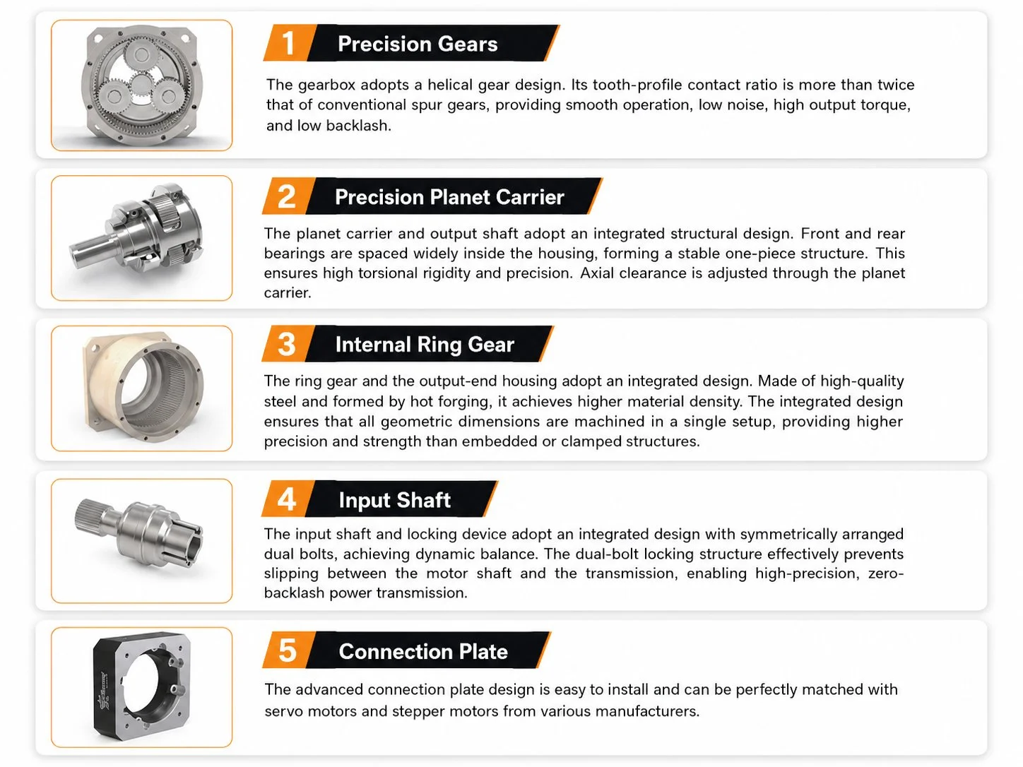
ข้อต่อทุกชิ้นในระบบขับเคลื่อนเซอร์โวล้วนเป็นชิ้นส่วนที่ต้องบำรุงรักษาและเป็นแหล่งที่มาของระยะคลายตัว ข้อต่อแบบเบลโลว์เริ่มต้นที่ 0.2–0.5 อาร์คมินเมื่อใหม่ และจะเพิ่มขึ้นตามรอบความล้าจากการบิด ข้อต่อแบบก้ามปูเริ่มต้นที่ 0.5–1.5 อาร์คมินและจะเพิ่มขึ้นเร็วกว่านั้น เอาต์พุตวงกลมสลักเกลียวของ EP-TNF จะแทนที่ข้อต่อด้วยส่วนต่อประสานโครงสร้างแบบตายตัว ค่าที่ได้รับการรับรองระยะคลายตัวของเกียร์บ็อกซ์คือระยะคลายตัวรวมของระบบทั้งหมด — ไม่มีส่วนร่วมของข้อต่อที่ต้องประเมิน วัด หรือขันให้แน่นเป็นระยะ สำหรับระบบที่มีงบประมาณสำหรับระยะคลายตัวรวม 5 อาร์คมิน EP-TNF P1 จะให้ค่าดังกล่าวเป็นค่าเดียวที่วัดได้และได้รับการรับรอง
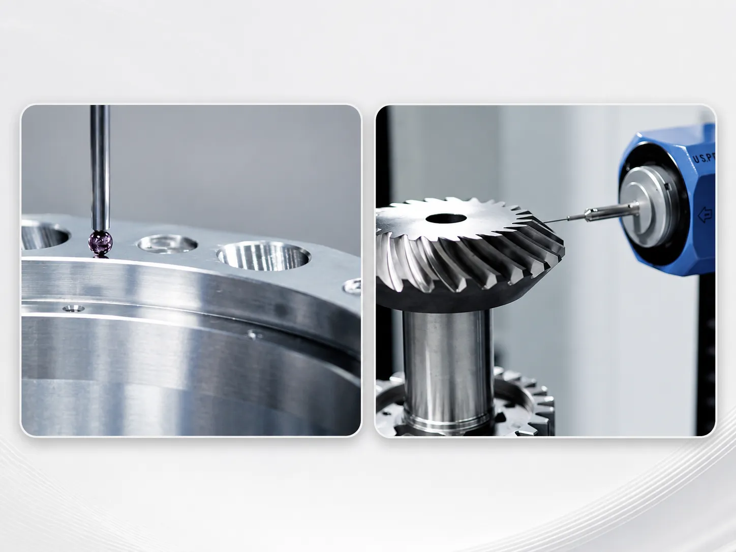
หน้าหน้าแปลนเอาต์พุตและตัวกำหนดตำแหน่งนำร่องจะถูกเจียรหลังจากประกอบเกียร์บ็อกซ์เสร็จสมบูรณ์ โดยอ้างอิงจากแกนหมุนจริง ค่าความคลาดเคลื่อนของแกนหมุน (Runout) ≤0.02 มม. เกิดขึ้นได้เนื่องจากจุดอ้างอิงในการเจียรคือคู่แบริ่งที่ประกอบแล้ว ไม่ใช่แกนออกแบบตามชื่อ ตัวกำหนดตำแหน่งนำร่องจะกำหนดตำแหน่งของดุมหรือตัวเรือนโต๊ะให้ตรงกับแกนหมุน วงกลมของสลักเกลียวช่วยในการยึดตามแนวแกนและส่งแรงบิด ทุกครั้งที่ติดตั้งเกียร์บ็อกซ์กลับเข้าไปในรูนำร่องเดิม ความแม่นยำของศูนย์กลางจะกลับคืนมาโดยอัตโนมัติโดยไม่ต้องปรับแนวด้วยเครื่องวัดระยะแบบหน้าปัด
แขนหุ่นยนต์แบบยื่นหรืออุปกรณ์จับยึดแบบหมุนจะสร้างแรงดัดที่ส่วนต่อประสานเอาต์พุต ในชุดเกียร์แบบเพลาส่งกำลัง แรงดัดนี้จะถูกต้านทานโดยระยะห่างของแบริ่งเพลาส่งกำลัง ซึ่งถูกจำกัดโดยความยาวของเพลาภายในตัวเรือน ในชุดเกียร์ EP-TNF แรงดัดจะถูกต้านทานโดยวงกลมของสลักเกลียวที่เส้นผ่านศูนย์กลางหน้าแปลนทั้งหมด (Ø80–292 มม. ขึ้นอยู่กับโครงสร้าง) กระจายไปทั่วสลักเกลียวหน้าแปลนทั้งหมด ระยะห่างของคานที่มีประสิทธิภาพในการต้านทานแรงดัดคือรัศมีของหน้าแปลน ซึ่งมีขนาดใหญ่กว่าระยะห่างของแบริ่งเพลาที่พิกัดแรงบิดที่เท่ากัน ส่งผลให้ความสามารถในการรับแรงดัดเอียงสูงขึ้น
ชุดเฟืองดาวเคราะห์เกลียวภายใน EP-TNF นั้นเหมือนกับ EP-TM ทุกประการเมื่อมีขนาดเฟรมเท่ากัน ประสิทธิภาพ ≥97% L1 / ≥94% L2 เท่ากัน — ไม่มีผลกระทบต่อประสิทธิภาพจากส่วนต่อประสานหน้าแปลน ความแตกต่างเล็กน้อยของระยะคลายตัว (EP-TNF P1 ≤5 arcmin เทียบกับ EP-TM P1 ≤3 arcmin) สะท้อนถึงรูปทรงเรขาคณิตของแบริ่งหน้าแปลนมากกว่าความแม่นยำของเฟืองที่ต่ำกว่า สำหรับการใช้งานที่เปรียบเทียบ EP-TM + ข้อต่อ กับ EP-TNF โดยตรง ตัวเลือก EP-TNF มักจะส่งผลให้ระยะคลายตัวของระบบโดยรวมต่ำกว่า เนื่องจากช่วยขจัดผลกระทบจากข้อต่อได้อย่างสมบูรณ์
ขนาดของหน้าแปลนเอาต์พุต EP-TNF เข้ากันได้กับมาตรฐานอินเทอร์เฟซข้อมือหุ่นยนต์ ISO 9409-1 ในขนาดเฟรมต่างๆ — TNF060 (Ø80 มม.) ตรงกับขนาด 50 และ TNF090 (Ø116 มม.) ตรงกับขนาด 80 これにより、フロットリントリントのフロ� ...��ントリントのフロットリントが実現します。 Korea Ever-Power จะยืนยันขนาดวงกลมรูยึดและขนาดการลงทะเบียนนำร่องที่เฉพาะเจาะจงเทียบกับขนาด ISO 9409-1 ที่ต้องการได้ในวันเดียวกันโดยไม่มีค่าใช้จ่ายเพิ่มเติม
การวัดระยะคลายตัว (backlash) ที่ระบุในใบรับรองการส่งมอบของ EP-TNF นั้น วัดที่หน้าหน้าแปลนด้านเอาต์พุต ที่แรงกดล่วงหน้า ±3% T₂ₙ โดยอ้างอิงจากแกนการหมุนของหน้าแปลนจริง ซึ่งเป็นจุดอ้างอิงเดียวกับส่วนต่อประสานของเครื่องจักร ค่าที่วัดได้จะถูกป้อนเข้าสู่ค่าความคลาดเคลื่อนของระบบโดยตรงโดยไม่ต้องแปลงใดๆ สำหรับเกียร์ทดรอบแบบเพลาส่งกำลัง ระยะคลายตัวจะวัดที่ปลายเพลา จากนั้นผู้ออกแบบเครื่องจักรจะต้องเพิ่มค่าความยืดหยุ่นของข้อต่อเพื่อให้ได้ระยะคลายตัวรวมของระบบ การวัดที่หน้าแปลนของ EP-TNF ช่วยลดขั้นตอนการคำนวณเพิ่มเติมนี้
อัตราส่วนที่มีให้เลือกและขนาดหน้าแปลนทางเข้ามอเตอร์
| เวที | อัตราส่วนที่มีอยู่ i | η | ปฏิกิริยาตอบโต้ P1 | เหมาะที่สุดสำหรับ |
|---|---|---|---|---|
| แอล1 ซิงเกิล | 3 · 4 · 5 · 6 · 7 · 8 · 10 | ≥97% | ≤5′ | ข้อต่อหุ่นยนต์, โต๊ะหมุน CNC, ตัวจัดตำแหน่งแบบขับตรง |
| แอล2 ดูอัล | 12 · 15 · 20 · 25 · 30 · 35 · 40 · 50 · 60 · 70 · 80 · 100 | ≥94% | ≤7′ | เซอร์โวอัตราทดสูง, ไดรฟ์ที่จับคู่แรงเฉื่อย |
ขนาดหน้าแปลนทางเข้ามอเตอร์ — TNF แบบขั้นตอนเดียว L1
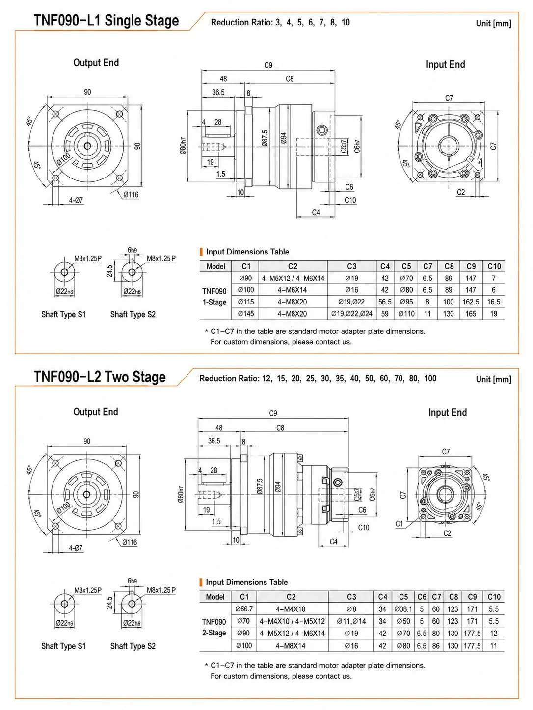
| เฟรม | เส้นผ่านศูนย์กลางหน้าแปลนทางออก | นักบินเครื่องยนต์ Ø (C1) | วงกลม/เกลียวของน็อตยึดมอเตอร์ (C2) | เพลาอินพุต Ø (C3) | ความลึก C4 | ความยาวรวม C9 |
|---|---|---|---|---|---|---|
| ทีเอ็นเอฟ060 | Ø80 | Ø66.7 / Ø70 / Ø90 | 4-M4×10 / M5×12 / M6×14 | Ø8 / Ø11 / Ø19 | 34 | 115 มม. |
| ทีเอ็นเอฟ090 | Ø116 | Ø90 / Ø100 / Ø115 / Ø145 | M5×12 – M8×20 | Ø19 / Ø16 / Ø19,22 | 42 | 147 มม. |
| ทีเอ็นเอฟ115 | Ø152 | Ø145 / Ø200 | 4-M8×20 / 4-M12×28 | Ø19.22 / Ø35 | 64 | 199 มม. |
| ทีเอ็นเอฟ142 | Ø186 | Ø145 / Ø200 | 4-M8×20 / 4-M12×28 | Ø22 / Ø35 | 72 | 252 มม. |
| ทีเอ็นเอฟ180 | Ø240 | Ø200 / Ø215 / Ø235 | 4-M12×28 / 4-M12×30 | Ø35 / Ø42 | 85 | 284 มม. |
| ทีเอ็นเอฟ220 | Ø292 | Ø200 / Ø215 / Ø235 | 4-M12×28 / 4-M12×30 | Ø35 / Ø42 / Ø55 | 109 | 358 มม. |
ขนาดเส้นผ่านศูนย์กลางรูยึดหน้าแปลน, ข้อกำหนดเกลียว และความลึกของร่องนำร่อง อ้างอิงจากแบบร่างขนาดของ Korea Ever-Power C1 = เส้นผ่านศูนย์กลางร่องมอเตอร์, C3 = เส้นผ่านศูนย์กลางเพลามอเตอร์ ขนาดอินพุต TNF180/220 สามารถกำหนดค่าได้ — โปรดระบุชนิดมอเตอร์เมื่อสั่งซื้อ
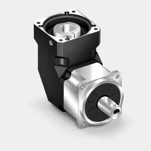
EP-TNF เทียบกับ EP-TM เทียบกับ EP-TMR — สามรูปแบบ แต่ความแม่นยำระดับเดียวกัน
EP-TM, EP-TNF และ EP-TMR ใช้ชุดเฟืองดาวเคราะห์แบบเกลียวเดียวกันและให้ระดับความแม่นยำที่เหมือนกัน การเลือกใช้ขึ้นอยู่กับรูปทรงเรขาคณิตของส่วนต่อประสานเอาต์พุตที่จำเป็นสำหรับการออกแบบเครื่องจักรเป็นหลัก
| คุณสมบัติ | อีพี-ทีเอ็ม | อีพี-ทีเอ็นเอฟ | อีพี-ทีเอ็มอาร์ |
|---|---|---|---|
| อินเทอร์เฟซเอาต์พุต | เพลาแบบมีร่อง/ทรงกลม | หน้าแปลนกลม | เพลาแบบมีร่อง/ทรงกลม มุม 90° |
| ทิศทางการส่งออก | แนวตรง (0°) | แนวตรง (0°) | มุมฉาก (90°) |
| ขนาดเฟรม | 042–220 | 060–220 เท่านั้น | 042–220 |
| ประสิทธิภาพ L1 | ≥97% | ≥97% | ≥95% |
| ปฏิกิริยาย้อนกลับ P1 (L1) | ≤3′ | ≤5′ | ≤6′ |
| ความต้านทานโมเมนต์เอียง | จำกัดเพลา | สูง (หน้าแปลนกว้าง) | ปานกลาง |
| แอปพลิเคชันเกาหลีที่ดีที่สุด | เฟืองและแร็ค, สกรูบอล, ข้อต่อขับเคลื่อน | หน้าแปลนหุ่นยนต์, โต๊ะหมุน, ตัวจัดตำแหน่งแบบติดตั้งโดยตรง | การเปลี่ยนทิศทาง 90° ในพื้นที่จำกัด |
ข้อกำหนด EP-TNF P1 ที่ ≤5 arcmin นั้นกว้างกว่า EP-TM P1 ที่ ≤3 arcmin เล็กน้อย นี่สะท้อนถึงช่วงแบริ่งเอาต์พุตที่กว้างกว่าในการออกแบบหน้าแปลน — คู่แบริ่งหน้าแปลนที่มีเส้นผ่านศูนย์กลางใหญ่กว่าทำให้เกิดเส้นทางความยืดหยุ่นในการบิดเพิ่มเติมเล็กน้อยเมื่อเทียบกับชุดแบริ่งเอาต์พุตเพลาขนาดกะทัดรัด ในระดับการใช้งาน ทั้ง ≤3 arcmin และ ≤5 arcmin ให้ความแม่นยำในการทำซ้ำต่ำกว่าหนึ่งอาร์คนาทีในการใช้งานการกำหนดตำแหน่งส่วนใหญ่ของเกาหลี หากต้องการ ≤1 arcmin ให้ระบุ ซีรี่ส์ EP-TEG ความแม่นยำสูงพิเศษ.
EP-TNF ในอุตสาหกรรมเกาหลี — การใช้งานที่สำคัญต่อหน้าแปลน 6 แบบ
ผู้ผลิตหุ่นยนต์ร่วมปฏิบัติงานจากเกาหลี (Rainbow Robotics, Doosan Robotics) กำหนดให้ใช้หน้าแปลนเอาต์พุตขนาดใหญ่ที่ข้อต่อไหล่และข้อศอก เพื่อเชื่อมต่อโดยตรงกับรางอลูมิเนียมของแขนหุ่นยนต์ TNF090/115 ที่ i=25–50 P1 เป็นการกำหนดค่ามาตรฐาน พื้นผิวหน้าแปลนทำหน้าที่เป็นพื้นผิวรองรับโครงสร้างสำหรับข้อต่อแขน — ไม่จำเป็นต้องใช้แหวนอะแดปเตอร์แยกต่างหาก ซึ่งช่วยลดมวลของแขนและการคำนวณความเฉื่อยที่แต่ละข้อต่อ ดูคู่มือการขับเคลื่อนข้อต่อหุ่นยนต์ →
ผู้ผลิตเครื่องมือกล CNC จากเกาหลี (Doosan Machine Tools, Hwacheon) ใช้ TNF115/142 ที่ i=50–100 สำหรับแกนหมุน B และ C ขอบหน้าแปลนขนาดใหญ่ (Ø152/Ø186 มม.) ให้ความแข็งแรงทางโครงสร้างที่จำเป็นในการยึดชิ้นงานไว้ที่หน้าโต๊ะภายใต้แรงตัด หน้าหน้าแปลนที่ผ่านการเจียระไน (ค่าเบี่ยงเบน ≤0.02 มม.) กำหนดความตั้งฉากของหน้าโต๊ะ ซึ่งส่งผลโดยตรงต่อความแม่นยำในการปรับเทียบเชิงมุม 5 แกน
โมดูลส่วนหน้าของอุปกรณ์ (Equipment Front End Modules หรือ EFEM) ในชุดเครื่องมือการผลิตของเกาหลี (ที่ใช้ใน Samsung Display, LGD) ใช้ TNF060/090 สำหรับแกนหมุนของหุ่นยนต์ลำเลียงเวเฟอร์ TNF060 ขนาดเล็ก (หน้าแปลน Ø80 มม., 1.3 กก.) พอดีกับพื้นที่ติดตั้ง EFEM ในขณะที่ให้ระยะคลายตัว P1 ที่จำเป็นสำหรับการจัดตำแหน่งร่องเวเฟอร์ที่แม่นยำ จาระบีที่ปิดผนึกช่วยขจัดปัญหาการเกิดอนุภาคจากการหล่อลื่นด้วยน้ำมัน ซึ่งอาจส่งผลกระทบต่อข้อกำหนดของห้องคลีนรูม ISO Class 3
เครื่องตัดเลเซอร์ไฟเบอร์ของเกาหลี (Han's Laser Korea, Bystronic Korea) ใช้ TNF090 หรือ TNF115 สำหรับแกนหมุนที่ใช้ในการกำหนดตำแหน่งชิ้นงานทรงท่อ ส่วนปลายหน้าแปลนจะติดตั้งโดยตรงกับแผ่นรองด้านหลังของหัวจับ – พื้นผิวหน้าแปลนที่ผ่านการเจียระไนจะช่วยให้หัวจับตั้งฉากกับแกนหมุน ซึ่งเป็นตัวกำหนดความตั้งฉากของการตัดบนโปรไฟล์ท่อกลม ที่ค่า i=25–50 เซอร์โวสามารถสร้างการเคลื่อนที่กำหนดตำแหน่งด้วยความเร็วสูง (360°/0.2 วินาที) เพื่อรอบการประมวลผลท่อที่มีประสิทธิภาพ
ผู้ผลิตอุปกรณ์ทางการแพทย์ของเกาหลี (GE Healthcare Korea และ Siemens Healthineers Korea) ใช้ TNF090/115 ในชุดขับเคลื่อนการหมุนของโครงเครื่องสแกน CT หน้าแปลนขนาดใหญ่ทำหน้าที่เป็นแบริ่งโครงสร้างสำหรับวงแหวนหมุนของโครงเครื่อง เสียงรบกวนต่ำ (≤60–63 dB) เป็นไปตามข้อกำหนดการติดตั้งในโรงพยาบาล และจาระบีที่ปิดผนึกช่วยลดความยุ่งยากในการเข้าถึงเพื่อบำรุงรักษาด้วยน้ำมันในตัวเรือนโครงเครื่องที่ปิดสนิท
ระบบ APC ของเครื่องจักรกลซีเอ็นซีของเกาหลีหมุน 180° เพื่อสลับพาเลทที่บรรจุและไม่บรรจุชิ้นงาน TNF115/142 ที่ i=20–40 ขับเคลื่อนการหมุนนี้ผ่านหน้าแปลนเอาต์พุตที่ติดตั้งโดยตรงกับดุมแท่นหมุนของ APC — ไม่มีเพลา ไม่มีข้อต่อ ไม่มีขั้นตอนการจัดตำแหน่งข้อต่อ หน้าแปลนของ TNF เป็นส่วนต่อประสานที่มีความแม่นยำสูงซึ่งกำหนดความแม่นยำของตำแหน่งพาเลทที่แกนหมุนของเครื่องจักร ความสามารถในการทำซ้ำของพาเลทขึ้นอยู่กับการเบี่ยงเบนของหน้าแปลนเอาต์พุตโดยตรง: การเบี่ยงเบนของหน้าแปลน TNF ≤0.02 มม. จะส่งผลให้เกิดข้อผิดพลาดในการกำหนดตำแหน่งของ APC น้อยกว่า 0.02 มม.
วิธีการอ่านรหัสแบบจำลอง EP-TNF
เกียร์ทดรอบดาวเคราะห์แบบเกลียว
060/090/115/142/180/220
L1: 3–10 · L2: 12–100
S1 = ทรงกลม · S2 = แบบมีร่อง
P1 ≤5′ · P2 ≤5–7′
ระบุมอเตอร์เมื่อสั่งซื้อ
ซีรี่ส์ EP-TNF เริ่มต้นที่เฟรม 060 และไม่รวมเฟรม 042 TNF042 ไม่ได้ระบุไว้ในแคตตาล็อกเดิมของ POROVIN เนื่องจากเฟรมขนาด 042 มม. เล็กเกินไปที่จะรองรับการออกแบบแบริ่งหน้าแปลนเอาต์พุตที่ความสามารถในการรับน้ำหนักที่ต้องการ หากแอปพลิเคชันของคุณต้องการเกียร์บ็อกซ์แบบหน้าแปลนเอาต์พุตในขนาดเฟรม 042 มม. โปรดติดต่อ Korea Ever-Power — หน่วยหน้าแปลนเอาต์พุตแบบกำหนดเองในขนาดเฟรมเล็ก ๆ มีให้บริการตามคำขอสำหรับโครงการ OEM ของเกาหลีที่มีปริมาณมากพอ
คำถามที่พบบ่อย — เกียร์ทดรอบแบบเฟืองดาวเคราะห์ EP-TNF ที่มีหน้าแปลนส่งกำลัง
การผสานรวมระบบขับเคลื่อน — ผลิตภัณฑ์และอุปกรณ์เสริมเสริม

อุปกรณ์เสริมที่สำคัญ — ซีรี่ส์ EP-TNF
ชุดน็อตดุม/หน้าแปลนเอาต์พุต
ตัวยึดตัวเข้ารหัส
ใบรับรองการต่อต้าน
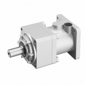
เพลาขับ CV — การส่งแรงบิดจากหน้าแปลนไปยังโหลดในระยะทางไกล
เมื่อแรงบิดเอาต์พุตของ EP-TNF ต้องไปถึงจุดรับน้ำหนักที่อยู่ห่างออกไป เช่น เพลาของแผงโซลาร์เซลล์ที่ทอดข้ามหลายช่อง, เฟืองแร็คแอนด์พิเนียนแกน X ของโครงเครนที่เยื้องศูนย์จากฐานมอเตอร์, หรือพูลเลย์ขับหัวสายพานลำเลียงหลายสถานี — เพลาขับความเร็วคงที่ ข้อต่อ CV นี้เชื่อมต่อหน้าแปลนเอาต์พุต EP-TNF กับองค์ประกอบขับเคลื่อนระยะไกล ข้อต่อ CV ช่วยดูดซับความคลาดเคลื่อนเชิงมุมในการติดตั้ง (±3–8° สำหรับเพลา CV อุตสาหกรรมมาตรฐาน) โดยไม่ส่งผ่านโมเมนต์ดัดแบบวงจรที่เพลาตัวกลางแบบแข็งจะกระทำต่อแบริ่งเอาต์พุตแม้ในกรณีที่มีความคลาดเคลื่อนเพียงเล็กน้อย ในเครื่องตัดเลเซอร์แบบโครงสร้างขนาดใหญ่ของเกาหลี การใช้งานร่วมกันนี้เป็นมาตรฐานในกรณีที่ไม่สามารถรับประกันการจัดตำแหน่งมอเตอร์กับแร็คได้อย่างสมบูรณ์แบบหลังจากการปรับระดับเครื่องจักร
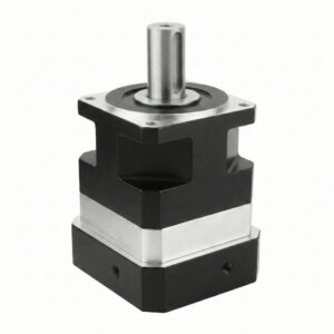
ชุดเกียร์ทดรอบแบบหนอน — เกียร์ทดรอบสูงแบบล็อคตัวเองได้ ขั้นที่สอง
สำหรับงานที่ต้องการอัตราส่วนรวมที่สูงกว่า i=100 พร้อมความสามารถในการล็อคตัวเอง — เช่น ชุดขับหมุนสำหรับยึดโหลดในแนวตั้ง โต๊ะดัชนีที่ต้องคงตำแหน่งไว้ด้วยแรงโน้มถ่วงระหว่างการเปลี่ยนดัชนี — a เกียร์ทดรอบแบบหนอน ส่วนปลายของ EP-TNF ให้การล็อคตัวเองและอัตราส่วนเพิ่มเติมที่หน้าแปลนขาออก หน้าแปลนขาออกของ EP-TNF สามารถยึดเข้ากับตัวเรือนขาเข้าของตัวลดเกียร์หนอนหลายแบบได้โดยตรง ช่วยลดข้อต่อกลางในระบบสองขั้นตอน การผสมผสานที่ได้รับการตรวจสอบแล้ว: EP-TNF ที่ i=10 (η≥97%) × หนอนที่ i=40 (η≈60–65%) = i รวม = 400 ประสิทธิภาพโดยรวม η≈58–63% ในกรณีที่ไม่ต้องการการล็อคตัวเอง EP-TNF เพียงอย่างเดียวที่ i=100 แบบสองขั้นตอน (η≥94%) เป็นโซลูชันแบบหน่วยเดียวที่มีประสิทธิภาพมากกว่า
รีวิวจากลูกค้าและผลการปฏิบัติงานภาคสนาม
5 ★
88%
4 ★
10%
≤3 ★
2%
EP-TNF115 P1 i=50 แท่นเลื่อนคู่สำหรับแกน C ของเครื่องจักร CNC 5 แกนรุ่นใหม่ของเรา หน้าแปลนเอาต์พุต Ø152 มม. ยึดติดกับตัวเรือนโต๊ะหมุนโดยตรง ไม่ต้องใช้ข้อต่อหรือแหวนอะแดปเตอร์ การออกแบบก่อนหน้านี้ใช้ EP-TM กับข้อต่อแบบเบลโลว์ ซึ่งข้อต่อสึกหรอถึง 0.8 อาร์คมินหลังจากใช้งาน 8,000 ชั่วโมง และเราต้องชดเชยในตัวควบคุม หน้าแปลน TNF แบบติดตั้งโดยตรง: ใช้งานมา 18 เดือน การวัดระยะคลายตัวยังคงไม่เปลี่ยนแปลงที่ 4.7 อาร์คมิน เทียบกับ 4.8 อาร์คมินในใบรับรองการส่งมอบ บริษัท Ever-Power จากเกาหลียืนยันว่าสามารถติดตั้งเข้ากับรูนำร่องของตัวเรือนโต๊ะของเราได้โดยตรง พอดีกับ H7/h6 ในวันเดียวกับที่สอบถาม
EP-TNF090 P1 i=25 สำหรับข้อต่อข้อมือ J4 บนหุ่นยนต์ร่วมปฏิบัติงาน 6 แกนที่เราสร้างขึ้นสำหรับอุตสาหกรรมทั่วไปของเกาหลี หน้าแปลนขนาด Ø116 มม. ต่อเข้ากับรูปแบบสลักเกลียวของข้อต่อแขนโดยตรง ไม่ต้องใช้ข้อต่อหรืออะแดปเตอร์หน้าแปลน ที่ i=25 อัตราส่วนความเฉื่อย J_load/J_motor = 0.12:1 ซึ่งปรับให้เข้ากับไดรฟ์เซอร์โวได้ทันที ค่าการเบี่ยงเบนของเอาต์พุตที่วัดได้ 0.018 มม. TIR หลังการประกอบ ซึ่งอยู่ในข้อกำหนด ≤0.02 มม. ที่น้ำหนักบรรทุก ≤3 กก. ข้อต่อทำงานได้อย่างไร้ที่ติเป็นเวลามากกว่า 12 เดือนและในหุ่นยนต์ร่วมปฏิบัติงาน 3 ตัว โดยไม่มีปัญหาการรับประกันใดๆ
EP-TNF180 P2 i=80 เกียร์ทดกำลังสองขั้นตอน สำหรับระบบขับเคลื่อนแกนเดียวแนวนอนของตัวติดตามแสงอาทิตย์ ในฟาร์มพลังงานแสงอาทิตย์ขนาด 2 เมกะวัตต์ ที่จังหวัดชอนบุก หน้าแปลนเอาต์พุตขนาด Ø240 มม. ยึดติดกับดุมแขนตัวติดตามโดยตรง ด้วยความสามารถในการรับแรงรัศมี Fr=14,800 N เกียร์ทดกำลังสามารถรับแรงลมเต็มที่บนแขนตัวติดตามขนาด 8 เมตร โดยไม่ต้องใช้ตลับลูกปืนเสริม การซีลระดับ IP65 และอุณหภูมิต่ำสุด −10°C สามารถใช้งานได้ดีตลอดฤดูหนาวของเกาหลีสองฤดู ติดตั้งไปแล้ว 68 ยูนิตทั่วทั้งไซต์งาน ไม่มีข้อบกพร่องใดๆ ในระยะเวลา 22 เดือน มีตัวเลือกตัวยึดสแตนเลสสำหรับสภาพแวดล้อมที่มีเกลือในพื้นที่ชายฝั่งทะเล
แบ่งปันประสบการณ์การยื่นขอรับทุน EP-TNF ของคุณ ติดต่อ Korea Ever-Power: [email protected]
ระบุรูปแบบหน้าแปลน EP-TNF ของคุณ
ระบุรูปแบบรูยึดหน้าแปลนด้านเอาต์พุต เส้นผ่านศูนย์กลางของตัวกำหนดตำแหน่งนำร่อง รุ่นมอเตอร์ และลักษณะการรับโหลด — บริษัท Korea Ever-Power จะตรวจสอบเฟรม EP-TNF อัตราส่วน และเกรดที่ถูกต้องพร้อมแบบร่างขนาด มีบริการสนับสนุนภาษาเกาหลีภายในวันทำการเดียวกัน
การสนับสนุนจากผู้เชี่ยวชาญด้านขั้วต่อหน้าแปลนกลม · ตอบกลับภายในวันเดียวกัน · ยืนยันความเข้ากันได้ตามมาตรฐาน ISO 9283
ข้อมูลเพิ่มเติม
| บรรณาธิการ | ซีเอ็กซ์เอ็ม |
|---|
ผลิตภัณฑ์ที่เกี่ยวข้อง
-
เกียร์ทดรอบแบบเฟืองดาวเคราะห์ความแม่นยำสูง รุ่น EP-ABR Series (EP-ABR042 ถึง EP-ABR220)
-
ชุดเกียร์แพลเนตารีแบบอินไลน์พร้อมเพลาส่งกำลังความแข็งแกร่งสูง รุ่น EP-AF (EP-AF042 ถึง EP-AF220 และรุ่น EP-AFX)
-
เกียร์ทดรอบแบบอินไลน์ความแม่นยำสูง หน้าแปลนสี่เหลี่ยมมาตรฐาน ซีรี่ส์ EP-AB (EP-AB042 ถึง EP-AB220)
-
ชุดเกียร์ทดรอบแบบดาวเคราะห์ประหยัดพลังงาน EP-BPGA Series — แบบหน้าแปลน A ติดตั้งบนมอเตอร์ (EP-BPGA040 ถึง EP-BPGA160)
-
ชุดเกียร์ทดรอบแบบดาวเคราะห์ความแม่นยำสูง EP-BAF Series — เพลาส่งกำลังความแข็งแรงสูง (EP-BAF042 ถึง EP-BAF220)
-
เกียร์ทดรอบแบบเฟืองดาวเคราะห์แรงบิดสูงสำหรับงานอุตสาหกรรมหนัก — ซีรี่ส์ PF (60/90/120/150PF)
-
เกียร์ทดรอบแบบเฟืองดาวเคราะห์ความแม่นยำสูงซีรีส์ VR สำหรับระบบส่งกำลังแบบโซ่
-
เกียร์ทดรอบแบบดาวเคราะห์ PLS Precision สำหรับระบบขับเคลื่อนโซ่ในอุตสาหกรรม


