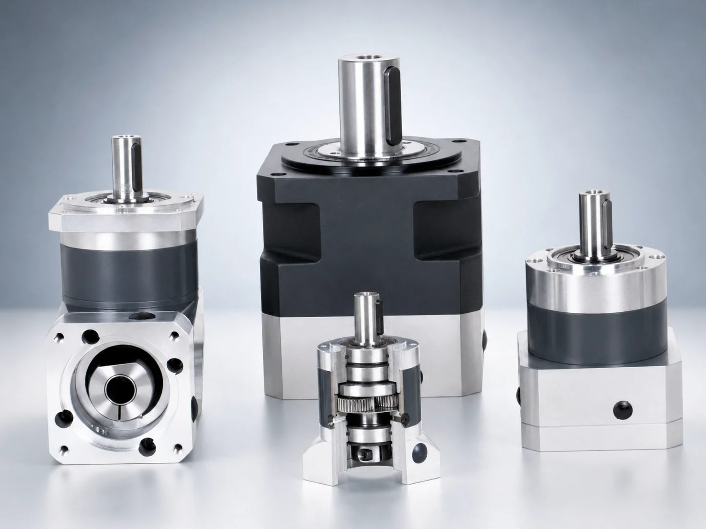
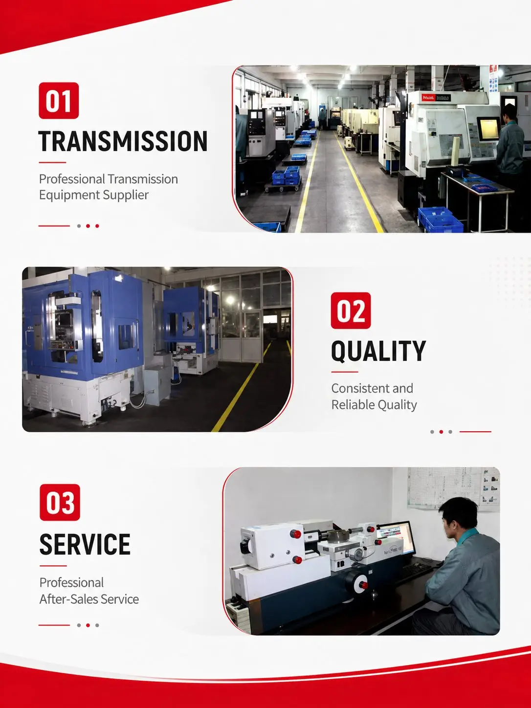
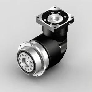
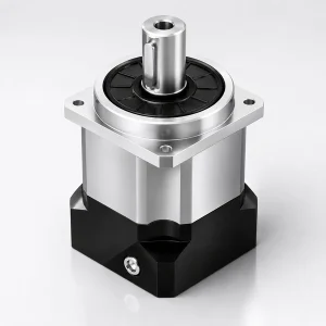
EP-ZDWF Series Right-Angle Input Square-Flange Precision Planetary Gearbox

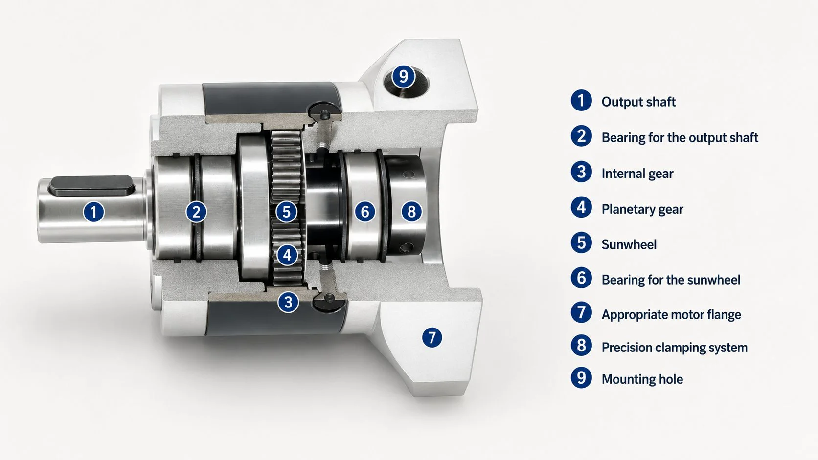
The EP-ZDWF Series is a right-angle input square-flange precision planetary gearbox combining a 90° bevel input stage with a square output mounting flange, available in four frame sizes from EP-ZDWF-60 to EP-ZDWF-160. It delivers rated output torque from 12 N·m up to 800 N·m with single-stage efficiency of 94%. The 90° bevel input positions the servo motor perpendicular to the output shaft, reducing total axial installation depth by 30–50% versus inline. The square flange (□60–□175 mm) bolts to any flat plate with 4 through-bolts — no precision bore required. EP-ZDWF is the most installation-versatile right-angle precision planetary gear reducer in the Korea Ever-Power EP series, combining both axial-depth and bore-machining savings in one unit.
EP-ZDWF Series — Right-Angle Input Square-Flange Precision Planetary Gearbox | 30–50% Axial Saving + No Bore, up to 800 N·m
EP-ZDWF is the Korea Ever-Power precision planetary gearbox that combines two installation advantages simultaneously: the 30–50% axial depth reduction of the right-angle bevel input (from the EP-ZDWE series right angle planetary gearbox) and the no-bore-required flat-plate mounting of the square output flange (from the EP-ZDF series). For Korean machine builders working with welded frames, aluminium extrusion structures, or laser-cut plate assemblies where both axial space and bore machining capability are constrained, EP-ZDWF eliminates both restrictions in a single product.
The EP-ZDWF series right-angle square-flange precision planetary gearbox and servo gear reducer from Korea Ever-Power is the intersection of the EP-ZDWE and EP-ZDF series in a single unit. It carries the right-angle 90° bevel input stage of EP-ZDWE — positioning the servo motor perpendicular to the output shaft to reduce total axial depth — and replaces the round output housing of EP-ZDWE with the square output flange (□60–□175 mm) of EP-ZDF, enabling direct flat-plate bolt-down mounting without a precision bore. All internal gear stages, torque ratings, backlash specifications, efficiency values, and lifetime lubrication characteristics are identical to EP-ZDWE.
Korean OEM machine builders who design machines around laser-cut flat-plate chassis or welded box-section frames — common in Korean AGV manufacturers, collaborative robot frame builders, and compact conveyor system integrators — find EP-ZDWF the optimal specification when the design brief simultaneously constrains both available axial depth behind the drive axis and the available machine shop operations for boring.
The Dual Installation Advantage — Why EP-ZDWF Combines Both Savings
INLINE ROUND-BORE (EP-ZDE) — TWO CONSTRAINTS
Problem 1: Long axial depth
Problem 2: Needs precision bore
→ Machining operation required
→ Motor + gearbox ~264 mm depth
RIGHT-ANGLE ROUND-BORE (EP-ZDWE) — ONE CONSTRAINT
[=ZDWE=]──▶ Round bore output
✔ Short axial depth (solved)
✘ Still needs precision bore
RIGHT-ANGLE SQUARE-FLANGE (EP-ZDWF) ★ — ZERO CONSTRAINTS
[=ZDWF=]──▶ □ Flat plate, 4 bolts
✔ Short axial depth (solved)
✔ No bore required (solved)
→ Drill 4 holes, bolt, done
When Both Constraints Apply — EP-ZDWF Is the Correct Specification
① Welded-Frame Compact Machines — No Boring, No Axial Space
Korean compact special-purpose machine builders who fabricate machine frames from welded structural steel box section face both constraints simultaneously: the welded frame has no machined bore and there is limited depth behind the axis for a motor to protrude inline. A laser-cut plate welded into the frame provides a flat mounting surface that accepts EP-ZDWF's square flange with 4 drill-and-tap holes; the right-angle bevel input places the motor within the available frame depth rather than projecting beyond it. EP-ZDWF solves the welded-frame installation with no post-weld machining operation and no extension of the machine envelope beyond the frame boundary.
② AGV & Mobile Robot Flat-Plate Chassis — Laser-Cut Structure, Minimal Depth
Korean AGV manufacturers typically build drive module frames from laser-cut aluminium or steel flat-plates assembled into a box structure. The drive axis is mounted through a plate, and the available chassis height (often 100–140 mm for low-profile AGVs) makes an inline motor impossible at any useful torque level. EP-ZDWF-60 or EP-ZDWF-80 mounts through the bottom plate with the square flange bolted to the plate face — 4 laser-cut holes in the plate cut simultaneously with the plate profile. The motor exits upward into the chassis interior. Total drive depth is the gearbox L1 only (150–184.5 mm for 60–80 frame, 1-stage), fitting within the chassis height with clearance for the motor body height within the chassis internal volume.
③ Aluminium Extrusion Profile Machines — Bracket-Free Direct Mounting
Korean automation system builders using 80×80 mm or 120×120 mm aluminium profile framing systems for pick-and-place, dispensing, and assembly machines use EP-ZDWF by mounting the square flange directly to a profile end-plate or gusset bracket. The T-slot profile cannot provide a precision bore, but a flat plate attached to the profile accepts EP-ZDWF's square flange bolted flat-face. The right-angle input allows the motor to exit along the profile axis rather than perpendicular to it, keeping the overall machine cross-section within the profile grid without requiring a custom oversized extrusion or a projecting motor overhang.
All Four EP Series Variants — Full Installation Comparison
| Criterion | EP-ZDE | EP-ZDF | EP-ZDWE | EP-ZDWF ★ |
|---|---|---|---|---|
| Motor orientation | Inline | Inline | 90° right-angle | 90° right-angle |
| Output flange | Round Φ (bore mount) | Square □ (plate mount) | Round Φ (bore mount) | Square □ (plate mount) |
| Axial depth saving | — | — | ✔ 30–50% shorter | ✔ 30–50% shorter |
| No bore needed | — | ✔ No bore | — | ✔ No bore |
| 1-stage efficiency | 96% | 96% | 94% | 94% |
| Torque / Backlash / IP | Identical within each frame size — same rated torque, same backlash per stage, IP54, lifetime lubrication, −25°C to +90°C | |||
EP-ZDWF Series — Complete Technical Specifications
① Rated Output Torque (N·m) — All Frame Sizes & Ratios
| Ratio | Stage | ZDWF-60 | ZDWF-80 | ZDWF-120 | ZDWF-160 |
|---|---|---|---|---|---|
| 3:1 | 1 | 12 | 40 | 80 | 400 |
| 4:1 | 1 | 16 | 50 | 110 | 450 |
| 5:1 | 1 | 16 | 50 | 110 | 450 |
| 8:1 | 1 | 15 | 45 | 100 | 400 |
| 10:1 | 1 | 12 | 40 | 80 | 305 |
| 9:1 | 2 | 40 | 100 | 210 | — |
| 12:1 | 2 | 40 | 100 | 210 | 700 |
| 16:1 | 2 | 44 | 120 | 260 | 800 |
| 20:1 | 2 | 44 | 120 | 260 | 800 |
| 25:1 | 2 | 40 | 110 | 230 | 700 |
| 32:1 | 2 | 44 | 120 | 260 | 800 |
| 40:1 | 2 | 40 | 110 | 230 | 700 |
| 64:1 | 2 | 40 | 100 | 210 | 700 |
| 60–512:1 | 3 | 40–44 | 100–120 | 210–260 | — |
② Load Capacity, Efficiency, Weight & Speed — Identical to EP-ZDWE
| Parameter | Unit | ZDWF-60 | ZDWF-80 | ZDWF-120 | ZDWF-160 |
|---|---|---|---|---|---|
| Max radial force | N | 450 | 900 | 2,100 | 6,000 |
| Max axial force | N | 225 | 450 | 1,050 | 3,000 |
| Efficiency — 1-stage | % | 94 (bevel input stage; vs 96% for inline EP-ZDE/ZDF) | |||
| Efficiency — 2-stage | % | 92 | |||
| Efficiency — 3-stage | % | 88 | |||
| Weight — 1-stage | kg | 1.7 | 4.4 | 12 | 36 |
| Weight — 2-stage | kg | 1.9 | 5 | 14 | 40 |
| Weight — 3-stage | kg | 2.1 | 5.5 | 16 | — |
| Torsional stiffness — 1-stage | N·m/arcmin | 1.5 | 4.5 | 10 | 38 |
| Torsional stiffness — 2-stage | N·m/arcmin | 2.5 | 6.5 | 13 | 43 |
| Noise (idle, 3,000 rpm) | dB(A) | 65 | 68 | 70 | 70 |
| Max input speed | rpm | 4,500 | |||
| Recommended input speed | rpm | 3,000 | |||
③ Backlash by Frame & Stage
| Stage | Unit | ZDWF-60 | ZDWF-80 | ZDWF-120 | ZDWF-160 |
|---|---|---|---|---|---|
| Backlash — 1-stage | arcmin | <30 | <25 | <25 | <25 |
| Backlash — 2-stage | arcmin | <35 | <30 | <30 | <30 |
| Backlash — 3-stage | arcmin | <40 | <35 | <35 | — |
④ General Specifications
| Parameter | Specification |
|---|---|
| Operating temperature | −25°C to +90°C |
| Protection rating | IP54 (IEC 60529) — dust-tight, splash-protected from any direction |
| Lubrication | Lifetime lubrication — factory-sealed, covers both bevel and planetary stages |
| Mounting orientation | Any — horizontal, vertical, inverted, any inclined angle |
| Motor input direction | 4 positions — left, right, up, down (specify on order, fixed at manufacture) |
| Input shaft clamping types | S: integral locking (default) · S1: locking ring · S2: keyway + clamping · K: keyway · A: custom |
| Output shaft tolerance | h7 — all frame sizes |
| Rated service life | 20,000 hours at rated load (L10 bearing life) |
| Instant stop torque | 2× rated output torque |
EP-ZDWF Series — Mechanical Dimensions (Unit: mm)
EP-ZDWF shares all body and input dimensions with EP-ZDWE. Orange rows show the ZDWF-specific square flange output dimensions. L1 and L12 are the same as EP-ZDWE for the corresponding frame size.
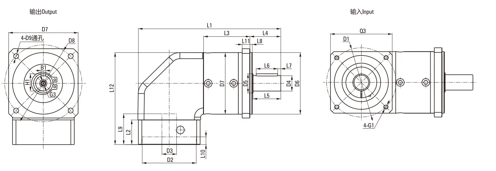
| Dimension | 60ZDWF | 80ZDWF | 120ZDWF | 160ZDWF |
|---|---|---|---|---|
| Square flange size D7 | □60 | □90 | □120 | □160 / □175 |
| Flange thickness L11 | 8 | 10 | 15 | 5 |
| Overall length L1 — 1-stage | 150 | 184.5 | 249.2 | 368 |
| Overall length L1 — 2-stage | 163 | 202.5 | 277 | 417.5 |
| Total height L12 (incl. input flange) | 93 | 119.5 | 167.5 | 229 |
| Output shaft diameter D4 | Φ14h7 | Φ20h7 | Φ25h7 | Φ40h7 |
| Input flange length L2 | 20 | 32 | 38 | 66 |
| Input flange Q3 (square) | □60 | □80 | □130 | □175 |
Installation Guide — EP-ZDWF Right-Angle Square-Flange Series
Combined Right-Angle + Square-Flange Mounting — Any Flat Surface, Any Orientation
EP-ZDWF installation combines the procedures of EP-ZDWF and EP-ZDF: the square flange bolts to any flat machine surface (no bore required), and the motor mounts perpendicular via the bevel input stage. Specify the motor input direction (left/right/up/down) at order time — fixed at manufacture.
Step-by-Step Installation Procedure
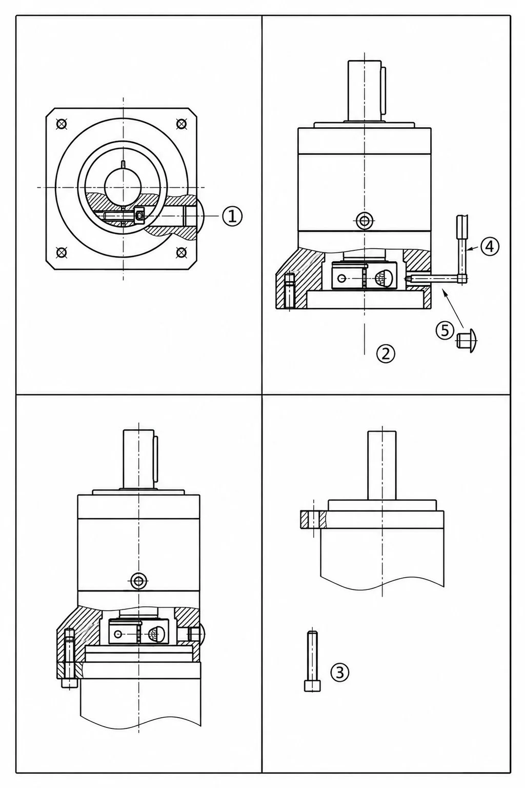
Confirm Input Direction, Flange Size & Model Code
Verify the EP-ZDWF model code includes the motor input direction (left/right/up/down), frame size (60–160), square flange size D7 (□60–□175), and input flange Q3 matching the servo motor front face. Confirm L12 (total height with motor input) fits within your machine section. Check that the square flange size and bolt-hole pattern are compatible with your machine plate before installation.
Prepare the Machine Plate — 4 Holes Only
Drill 4 mounting holes in the machine plate at the correct PCD (see EP-ZDF dimension table for matching frame size — D8 and D9 values). No precision bore is required. Ensure the mounting surface flatness is within 0.02 mm. For laser-cut plates, confirm the bolt-hole positions are included in the cutting file at the plate design stage — no secondary machining needed. Clean the surface to remove burrs before mounting.
Motor Coupling — Perpendicular Bevel Input
Insert the servo motor shaft fully into the perpendicular bevel input bore until the motor face contacts the input flange squarely. Tighten S-type locking screws evenly in a cross pattern. Verify no axial gap between motor face and input flange — if the motor shaft is shorter than the bore depth, use a spacer ring. The clamping input works with or without a motor shaft keyway.
Square Flange Mounting — 4-Bolt Pattern
Place the square flange face against the machine plate, aligning the 4 through-bolt holes with the plate hole pattern. Insert class 8.8 bolts (10.9 recommended for high-cycle applications), hand-tighten, verify full face contact, then torque evenly in cross pattern. Use thread-locking compound (medium-strength) for vibration-prone applications. Verify motor body has clearance in the perpendicular direction before final torquing.
Output Shaft, Load & Clearance Check
Connect load coupling to h7 output shaft D4 using standard procedure. Confirm radial load at shaft centre (L/2) does not exceed max radial force (e.g. 900 N for 80-frame). Manually rotate through full output revolution and confirm motor body clears all machine structure in the perpendicular direction. Route servo motor cables parallel to the machine travel axis, using a cable chain with adequate loop length to accommodate any axis movement range without cable tension.
No-Load Run-In, Bolt Re-torque & Bevel Warm-Up
Run no-load for 30 minutes at ≤50% rated input speed. After run-in: (1) re-check 4 flange bolt torque values — thermal cycling may cause slight joint settling; (2) a light bevel stage hum during the first 10–15 minutes is normal run-in behaviour; (3) verify system backlash via servo drive feedback. Record as installation baseline. The sealed lifetime lubrication requires no further servicing after this run-in procedure.
⚠ Installation Cautions: Motor input direction is fixed at manufacture — specify correctly when ordering. Square flange face must have full contact with the machine plate — a gap concentrates bolt load and risks flange fatigue. Do not apply axial force to the bevel input shaft during motor installation. Never exceed 4,500 rpm input speed. The sealed housing has no grease port — do not add lubricant externally.
✔ Zero Maintenance — Both Stages Covered: The factory-sealed lifetime lubrication covers both the bevel input stage and the planetary gear stages in a single housing. No separate bevel gear oil, no scheduled lubrication, no re-greasing required over the 20,000-hour rated life. Re-check the 4 flange mounting bolts at the first 5,000-hour inspection alongside the visual lip seal check — this is the only periodic maintenance action for EP-ZDWF.
Applications — EP-ZDWF Right-Angle Square-Flange Planetary Gearbox in Korean Compact Platform Designs
Low-Profile AGV Drive Modules — Laser-Cut Chassis, Minimal Height
Korean AGV manufacturers building low-profile warehouse AMRs with a chassis height of 100–150 mm use EP-ZDWF-60 and EP-ZDWF-80 for drive wheel servo reductions. The square flange bolts to the bottom chassis plate through 4 laser-cut holes — no boring, no secondary machining — and the motor exits upward into the chassis interior through the available 100–150 mm chassis height. Total gearbox axial depth below the chassis plate is the L1 dimension only (150–184.5 mm for 60–80 frame, 1-stage), which places the drive wheel at the correct height relative to the floor. Korean AGV manufacturers in Hwaseong, Incheon, and Ansan report EP-ZDWF enabling low-profile AMR designs that compete directly with purpose-built AGV gear units at a fraction of the custom tooling cost.
Welded-Frame Compact Special-Purpose Machines
Korean special-purpose machine builders fabricating welded steel box frames for dedicated assembly, testing, or material handling equipment use EP-ZDWF where both the axial space and the bore machining capability are unavailable. A laser-cut insert plate welded into the frame provides the flat mounting surface for EP-ZDWF's square flange. The right-angle bevel input positions the motor within the frame depth rather than projecting beyond the frame boundary. This is particularly common in Korean EV battery module assembly machines, where the machine footprint is tightly constrained by the production cell layout and bore machining of welded assemblies is impractical.
Aluminium Profile Automation Cells — No Secondary Machining
Korean automation system integrators building reconfigurable assembly and dispensing cells from 80×80 or 120×120 mm aluminium profile framing specify EP-ZDWF for servo drive axes on the profile structure. The square flange bolts to an end-plate or gusset attached to the profile — no bore possible in the profile itself — and the motor exits along the profile section axis, keeping the overall drive package within the profile grid without oversized brackets. For the round-flange right-angle variant used with custom-bored profile blocks, see the EP-ZDWE series right angle planetary gearbox.
Collaborative Robot Wrist — Square-Flange Plate-Mount Structure
Korean collaborative robot manufacturers using laser-cut carbon-fibre or aluminium plate assemblies for robot arm structure (rather than cast or machined arm links) use EP-ZDWF for wrist roll and wrist pitch joints. The square flange bolts to the plate assembly without requiring a precision bore that would be impractical in thin-plate composite structures. The right-angle input routes the motor parallel to the arm link, controlling the wrist outer diameter to the gearbox body size (□60–□90 mm). For applications where the arm structure can accommodate a round bore, the EP-ZDWE round-flange version planetary gearbox provides equivalent performance.
Narrow-Profile Packaging Machine Bracket Modules
Korean packaging machinery OEMs designing servo-actuated filling and sealing stations for narrow-pitch carousel or chain-conveyor packaging lines use EP-ZDWF-60 and EP-ZDWF-80 for bracket-mounted servo actuators where both the bracket footprint and the available depth behind the mounting plate are constrained. The square flange enables the entire motor-gearbox module to be replaced as a bolted assembly in a single maintenance operation — without removing the bracket from the machine or performing any bore-alignment procedure. The right-angle bevel input routes the motor along the machine structure rather than projecting it into the operator access zone.
Solar Tracker Slew Drives — Flat-Plate Mounting, Lateral Motor
Korean solar tracker manufacturers designing single and dual-axis trackers with flat steel tube or angle-iron mounting structures for utility-scale solar farms in Korea, Vietnam, and Southeast Asia use EP-ZDWF-120 and EP-ZDWF-160 for the azimuth and elevation axis drives. The square flange bolts directly to a flat mounting plate welded onto the tracker torque tube assembly — no machined bore on the field-fabricated steel structure. The right-angle bevel input routes the servo motor laterally along the torque tube rather than projecting it perpendicular to the tracker panel surface, reducing wind load on the drive assembly and keeping the motor within the tracker's structural shadow. IP54 sealing and the −25°C to +90°C operating range cover Korean outdoor tracker operating conditions year-round.
Quality Certifications & Testing Standards
- ✔Right-angle servo gearbox bevel stage and square flange face flatness verified per production batch
- ✔Backlash measured per unit at ±3% of rated output torque — measurement certificate with every order
- ✔Full-load torque test at rated output torque for each unit before shipment
- ✔IP54 ingress verification per IEC 60529 — every production batch
- ✔Material certificate and dimensional drawing provided with every delivery

Why Korean Engineers Specify Korea Ever-Power EP-ZDWF
🔧
Both Installation Constraints Resolved — One Specification
When a Korean machine design is simultaneously constrained by available axial depth and unavailable bore machining, EP-ZDWF resolves both with a single product specification. No separate bracket design to redirect the motor, no boring jig for the welded frame, no split between two gearbox series in the same machine. One planetary gearbox part number, two installation problems solved.
🔲
Square Flange in Laser-Cut Plate — Zero Secondary Operations
For Korean machine builders using laser-cut flat-plate chassis as the primary structure, the EP-ZDWF bolt-hole pattern can be cut into the plate simultaneously with the plate profile — 4 holes, no secondary drill operation, no bore tolerance to machine. The gearbox is a drill-and-bolt installation on the same flat plate that forms the machine chassis structure.
📐
30–50% Axial Depth Reduction — Same Saving as EP-ZDWE
The axial space saving of EP-ZDWF is identical to EP-ZDWE — the right-angle bevel input stage operates identically in both. Korean AGV and compact machine designers who chose EP-ZDWF over EP-ZDWF because their structure uses flat plates rather than bore mounts receive exactly the same axial depth reduction in the final installation.
🔒
Lifetime Lubrication — Bevel + Planetary, One Sealed Housing
The factory-sealed lifetime grease covers the complete EP-ZDWF gearbox — both the bevel input stage and the planetary gear stages — in a single sealed unit. No separate bevel gear oil reservoir, no oil level maintenance, no lubrication access port. Korean machine builders who mount EP-ZDWF in locations with restricted maintenance access (inside AGV chassis, within conveyor frame sections) benefit from the zero-maintenance design across the 20,000-hour rated life.
🔄
4 Input Directions — Optimal Cable Routing for Any Platform Layout
EP-ZDWF's 4-position motor input (left/right/up/down) allows Korean platform designers to route the servo motor cable in the direction that avoids obstruction — into the AGV chassis interior, along the machine column, or parallel to the conveyor frame. For designs that iterate through multiple motor routing options during development, Korea Ever-Power supplies EP-ZDWF sample units in each input direction for layout evaluation before committing to production tooling.
🇰🇷
Korean Engineering Support — Flange Matching, Layout Review & Input Direction
Korea Ever-Power's Korean application team assists with EP-ZDWF frame size selection, square flange size matching to machine plate dimensions, input direction selection, axial depth calculation versus inline alternatives, and motor input flange specification — in Korean. For Korean AGV and special-purpose machine builders evaluating the dual-advantage EP-ZDWF, the team provides a full installation envelope calculation and plate hole pattern confirmation at no charge before order placement.
Customer Reviews & Application Feedback
5 ★
87%
4 ★
11%
≤3 ★
2%
EP-ZDWF-60 at 10:1 single-stage for a 130 mm chassis-height low-profile AMR. Our chassis is laser-cut 4 mm aluminium plate — the bolt holes for EP-ZDWF are included in the cutting file at zero additional cost. Previous design used a competitor right-angle gearbox with a round output bore that required a precision-bored adapter plate; adding that adapter plate added 18 mm to the chassis height, pushing us over our 130 mm target. EP-ZDWF bolts directly to the chassis plate without the adapter, keeping us at 129 mm. We're producing 300+ AMR units per year; at this volume, eliminating the adapter plate saves 12 minutes of assembly time and approximately 850 KRW per unit in hardware cost. Korea Ever-Power confirmed our chassis plate hole pattern was compatible in 3 hours.
EP-ZDWF-80 at 20:1 two-stage for a battery module stacking robot on a welded steel base frame. Frame is fabricated from 100×100 mm welded box section — no machining facility on-site. We needed a servo gear reducer for the stacking head Z-axis drive where both the column depth (220 mm available) and the bore machining capability were unavailable. EP-ZDWF-80 with motor-right input direction fit exactly within 202.5 mm (2-stage L1), motor exiting into the available lateral space within the column. We welded a 10 mm laser-cut insert plate into the frame, drilled 4 holes, bolted the gearbox — total installation time 45 minutes per axis including motor coupling. 14 machines deployed, now running 18 months with zero gearbox issues.
EP-ZDWF-60 at 16:1 two-stage for the wrist pitch joint of a carbon-fibre plate robot arm. Our arm structure is CNC-milled 3 mm CFRP plate — precision boring is impractical in thin CFRP. EP-ZDWF square flange bolts to a titanium insert bonded into the plate assembly, the motor exits along the forearm axis via the right-angle input. The Korea Ever-Power application team provided the input direction (motor-up) and the exact input flange for our Delta servo motor within 6 hours of sending the motor drawing. Wrist pitch joint outer dimension: 74 mm — previously impossible with inline drive at this torque level. Now 11 months in operation on a food-grade coating robot; lifetime sealed grease is essential for our cleanroom compliance.
Share your EP-ZDWF application experience. Contact Korea Ever-Power: [email protected]
Related Products in the Korea Ever-Power Range
The EP-ZDWF is the right-angle input, square-flange variant in the Korea Ever-Power precision planetary gearbox EP series. The following series address applications where only one of the two EP-ZDWF advantages is required, or where higher torque capacity is needed.
EP-ZDWE — Right-Angle, Round Flange
Same right-angle bevel input and torque/backlash specifications as EP-ZDWF, with a round (circular) output flange for bore-mount installation. Choose EP-ZDWE when axial space saving is the priority but a precision bore is available — round flange provides better radial load support in some designs.
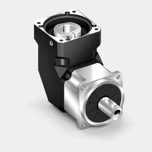
EP-ZDF — Inline Input, Square Flange
Same square flange output and torque/backlash specifications as EP-ZDWF, with an inline coaxial motor input. Choose EP-ZDF when no-bore plate mounting is required but axial space is not constrained — and get 96% single-stage efficiency (vs 94% for EP-ZDWF) plus <8 arcmin backlash (vs <25–30 arcmin for EP-ZDWF).
EP-ZDS — High Stiffness, Heavy Load
When EP-ZDWF-160 at 800 N·m is insufficient — EP-ZDS delivers up to 1,800 N·m (190-frame) with inline input, square flange, IP65 protection, torsional stiffness up to 130 N·m/arcmin, and 28,000 N maximum axial force. Note: EP-ZDS is inline input only; for heavy loads with right-angle input requirements, contact Korea Ever-Power for a custom solution.
Frequently Asked Questions
Additional information
| Editor | Cxm |
|---|
Related products
-
EP-ADR Series Right-Angle Round Flange Precision Planetary Gearbox (EP-ADR047 to EP-ADR255)
-
EP-ABR Series Right-Angle Square Flange Precision Planetary Gearbox (EP-ABR042 to EP-ABR220)
-
EP-AF Series High-Rigidity Output Shaft Inline Planetary Gearbox (EP-AF042 to EP-AF220, and EP-AFX Variant)
-
EP-AB Series Standard Square Flange High-Precision Inline Planetary Gearbox (EP-AB042 to EP-AB220)
-
EP-BAF Series High-Precision Planetary Gearbox — High-Rigidity Output Shaft (EP-BAF042 to EP-BAF220)
-
High-Precision Compact Planetary Gearbox for Servo Integration — PLS Series (PLS70–PLS190)
-
Chain Drive Planetary Gearboxes – EPW Series
-
EPL Double Shaft Planetary Gearbox for Chain Drive Systems


