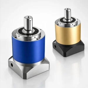
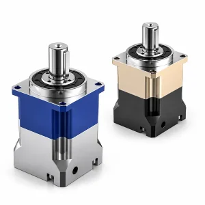
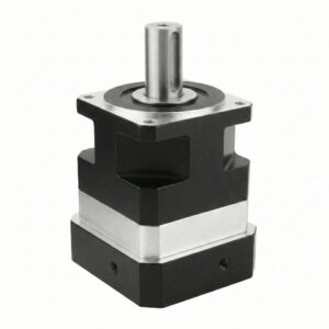
Ελικοειδές πλανητικό κιβώτιο ταχυτήτων EP-TNR με ορθογώνια στρογγυλή φλάντζα

Ο EP-TNF σας δίνει μια μεγάλη φλάντζα αλλά τοποθετεί τον κινητήρα εν σειρά πίσω από αυτήν. EP-TMR Διπλώνει τον κινητήρα κατά 90° αλλά η έξοδος γίνεται μέσω ενός άξονα. Το EP-TNR συνδυάζει και τα δύο — η τοποθέτηση του κινητήρα κατά 90° εξοικονομεί αξονικό βάθος, η στρογγυλή φλάντζα εξόδου παρέχει τη διεπαφή του δομικού μπουλονιού.
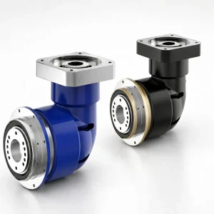
Σειρά EP-TNR — Πλανητικό κιβώτιο ταχυτήτων με στρογγυλή φλάντζα ορθής γωνίας | Πλαίσια 060–220 mm, i=3–200, έως 2.000 N·m
Όταν ένας σχεδιασμός μηχανής απαιτεί ο σερβοκινητήρας να εξέρχεται κάθετα στον άξονα φορτίου και Το φορτίο πρέπει να βιδώνεται απευθείας σε μια επιφάνεια φλάντζας μεγάλης διαμέτρου — αντί να σφίγγεται σε έναν άξονα — το EP-TNR είναι η σωστή διαμόρφωση. Ένας σύνδεσμος ρομποτικού βραχίονα που βιδώνεται στην επιφάνεια εξόδου του κιβωτίου ταχυτήτων, ένα περιστροφικό τραπέζι CNC με περίβλημα στρογγυλής οπής στο οποίο εδράζεται ο καταχωρητής πιλότου του κιβωτίου ταχυτήτων, μια φλάντζα στήριξης κεφαλής ευρετηρίου άμεσης κίνησης: αυτές οι εφαρμογές χρειάζονται έναν κύκλο μπουλονιού, όχι ένα άκρο άξονα, και χρειάζονται τον κινητήρα έξω από το αξονικό περίβλημα. Το EP-TNR καλύπτει και τις δύο απαιτήσεις σε μία μόνο σφραγισμένη μονάδα σε έξι μεγέθη πλαισίου από 060 έως 220 mm.
Σειρά EP-TNR — Πλήρεις τεχνικές προδιαγραφές
① Ονομαστική ροπή και ταχύτητα εξόδου — Και τα 6 καρέ
| Παράμετρος | Μονάδα | Στάδιο | TNR060 | TNR090 | TNR115 | TNR142 | TNR180 | TNR220 |
|---|---|---|---|---|---|---|---|---|
| Ονομαστική ροπή T₂ₙ | N·m | L1 (i=3–20) | 40–60 | 130–160 | 208–330 | 342–650 | 588–1.200 | 1.140–2.000 |
| L2 (i=12–200) | 40–60 | 130–160 | 208–330 | 342–650 | 588–1.200 | 1.140–2.000 | ||
| Μέγιστη ροπή T₂max | N·m | L1/L2 | 3 × T₂ₙ | |||||
| Ονομαστική ταχύτητα εισόδου nₙ | στροφές/λεπτό | L1/L2 | 5,000 | 4,000 | 4,000 | 3,000 | 3,000 | 2,000 |
| Μέγιστη ταχύτητα εισόδου n₁max | στροφές/λεπτό | L1/L2 | 10,000 | 8,000 | 8,000 | 6,000 | 6,000 | 4,000 |
| Αντίστροφη κίνηση P1 (σύνολο στην έξοδο) | arcmin | L1 (i=3–20) | ≤ 10 λεπτά του τόξου | |||||
| Αντίδραση P2 | arcmin | L1 / L2 | ≤ 12 λεπτά τόξου (L1) / ≤ 12 λεπτά τόξου (L2) | |||||
| Στρεπτική ακαμψία | N·m/αψίδα λεπτό | L1 | 7 | 14 | 25 | 50 | 145 | 225 |
| Επιτρεπόμενη ακτινική δύναμη Fρ ¹ | Β | L1/L2 | 1,530 | 3,250 | 6,700 | 9,400 | 14,500 | 50,000 |
| Επιτρεπόμενη αξονική δύναμη Fένα | Β | L1/L2 | 765 | 1,625 | 3,350 | 4,700 | 7,250 | 25,000 |
| Απόδοση η | % | L1 / L2 | ≥ 95% (L1) / ≥ 92% (L2) | |||||
| Βάρος | κιλά | L1 / L2 | 2.1 / 2.5 | 6.4 / 7.8 | 13 / — | 24,5 / — | 51 / 54 | 83 / 95 |
| Θόρυβος (3.000 σ.α.λ., χωρίς φορτίο) | dB(A) | L1/L2 | ≤63 | ≤65 | ≤68 | ≤70 | ≤72 | ≤74 |
¹ Ακτινική δύναμη στην κεντρική γραμμή του άξονα (x=L/2xL). Μειώνεται για έκκεντρη φόρτιση — εφαρμογή συντελεστή θέσης Kb. Συνδυασμένος: Fa ≤ 0,2×Fr, Fa_max ≤ 0,1×Fr.
−10°C έως +90°C
Πρότυπο IP65
Σφραγισμένο γράσο — εφ' όρου ζωής
20.000+ ώρες S1
Αριστερά / δεξιά / πάνω / κάτω
S1 στρογγυλό / S2 με κλειδί
Κατανόηση της οπισθοδρόμησης EP-TNR: γιατί η σωστή προδιαγραφή είναι ≤10 λεπτά τόξου P1
Η αντίστροφη κίνηση EP-TNR ≤10 λεπτά τόξου (P1, μονοβάθμιο) είναι το συνδυασμένο σύνολο στη φλάντζα εξόδου — περιλαμβάνει τη συνεισφορά της πλανητικής βαθμίδας και τη συνεισφορά της σπειροειδούς κωνικής βαθμίδας που μετρώνται μαζί στο ίδιο σημείο αναφοράς. Το EP-TNF P1 καθορίζει ≤5 λεπτά τόξου επειδή δεν έχει κωνική βαθμίδα. Η διαφορά είναι το γωνιακό διάκενο της ίδιας της κωνικής βαθμίδας — περίπου 4–6 λεπτά τόξου για ένα ζεύγος σπειροειδών κωνικών αξόνων ακριβείας. Αυτό δεν είναι έλλειψη ποιότητας. είναι η εγγενής φυσική της προσθήκης αλλαγής κατεύθυνσης 90°. Για τους σερβοάξονες όπου ο κωδικοποιητής ανάδρασης θέσης βρίσκεται στον άξονα του κινητήρα και ο βρόχος ελέγχου κλείνει στον κινητήρα, αυτά τα 10 λεπτά τόξου αντισταθμίζονται σε μεγάλο βαθμό από τον βρόχο σερβο. Για άξονες όπου ο κωδικοποιητής βρίσκεται κατάντη του κιβωτίου ταχυτήτων (γραμμική κλίμακα, περιστροφικός κωδικοποιητής στον άξονα φορτίου), το πραγματικό μη αντισταθμισμένο σφάλμα τοποθέτησης είναι η σχετική παράμετρος — και ≤10 λεπτά τόξου στη φλάντζα εξόδου EP-TNR αντιστοιχεί σε γραμμικό σφάλμα ≤0,15 mm σε ακτίνα 100 mm, εντός της ανοχής τοποθέτησης των περισσότερων κορεατικών βιομηχανικών εφαρμογών χειρισμού μεταφορικών ταινιών, συσκευασιών και υλικών.
② Διαθέσιμες σχέσεις μετάδοσης
| Στάδιο | Διαθέσιμες Αναλογίες i | η | Π1 | Κατάλληλο για |
|---|---|---|---|---|
| Μονόκλινο L1 | 3 · 4 · 5 · 6 · 7 · 8 · 10 · 14 · 20 | ≥95% | ≤10′ | Πυργίσκος εργαλείων CNC, συμπαγής κίνηση μεταφορικού ιμάντα, συμπαγές περιτύλιγμα ρομποτικής σύνδεσης |
| Διπλό L2 | 12 · 15 · 20 · 25 · 30 · 35 · 40 · 50 · 60 · 70 · 80 · 100 · 120 · 140 · 160 · 200 | ≥92% | ≤12′ | Αντιστοίχιση αδράνειας βαθιάς αναλογίας, εξαιρετικά αργές κινήσεις περιστροφής, μεταφορικός κοχλίας |
Το πρόβλημα γεωμετρίας εγκατάστασης — Γιατί πρέπει να συνυπάρχουν η στρογγυλή φλάντζα και οι 90°
Σε αυτήν την οικογένεια προϊόντων διατίθενται τρεις διαμορφώσεις κιβωτίου ταχυτήτων. Κάθε μία επιλύει έναν διαφορετικό χωρικό περιορισμό. Η κατανόηση του γιατί ένας σχεδιαστής μηχανών επιλέγει το EP-TNR αντί για το EP-TNF ή το EP-TMR απαιτεί την κατανόηση της ακριβούς γεωμετρικής σύγκρουσης που επιλύει κάθε διαμόρφωση.
ΔΙΑΣΥΝΔΕΣΗ ΕΞΟΔΟΥ × ΚΑΤΕΥΘΥΝΣΗ ΚΙΝΗΤΗΡΑ — ΤΡΕΙΣ ΔΙΑΜΟΡΦΩΣΕΙΣ
[ Κινητήρας ]──▶[ Πλανητικός ]──▶( Στρογγυλή φλάντζα )
Κινητήρας σε σειρά · άξονας + φλάντζα στον ίδιο άξονα
↓Κινητήρας
[ Πλανητικό + Λοξότμηση ]──▶ Στρογγυλός άξονας
↓Κινητήρας
[ Πλανητικό + Λοξότμηση ]──▶( Στρογγυλή φλάντζα )
Κάθετος κινητήρα · έξοδος φλάντζας
Όταν το αξονικό βάθος πίσω από την έξοδο είναι περιορισμένο ΚΑΙ το φορτίο βιδώνεται σε μια επιφάνεια φλάντζας
Αυτή είναι η περίπτωση χρήσης του EP-TNR. Μια στήλη μηχανής CNC 5 αξόνων με περιορισμένο βάθος πίσω από την περιστροφική τράπεζα του άξονα Β δεν μπορεί να φιλοξενήσει ένα EP-TNF με τον κινητήρα πίσω από αυτό — ο κινητήρας επεκτείνει το συγκρότημα πέρα από το δομικό περίβλημα της στήλης. Το EP-TMR εξοικονομεί αξονικό βάθος αλλά εξάγει μέσω ενός άξονα, απαιτώντας μια πρόσθετη σύζευξη μεταξύ του άξονα και της πλήμνης της περιστροφικής τράπεζας. Το EP-TNR τοποθετεί τον καταχωρητή πιλότου του απευθείας στην οπή του περιβλήματος της τράπεζας, ο κύκλος του μπουλονιού ασφαλίζει την πλήμνη της τράπεζας στην επιφάνεια της φλάντζας και ο κινητήρας εξέρχεται πλευρικά εντός του πλάτους της στήλης. Χωρίς σύζευξη, χωρίς υπέρβαση βάθους.
Όταν μια ρομποτική άρθρωση καρπού απαιτεί τόσο συμπαγές βάθος όσο και δομική διεπαφή φλάντζας
Οι αρθρώσεις καρπού J4–J6 του συνεργατικού ρομπότ λειτουργούν σε μια περιορισμένη εξωτερική διάμετρο που καθορίζεται από τη διατομή του βραχίονα. Ένα EP-TNF στον καρπό επεκτείνει το ενεργό μήκος του βραχίονα προς τα πίσω κατά το μήκος του σώματος του κινητήρα, μειώνοντας την αναλογία εμβέλειας προς βάθος του ρομπότ. Η τοποθέτηση του κινητήρα στο EP-TNR κάθετα στον άξονα του καρπού διατηρεί το μήκος του βραχίονα ρυθμιζόμενο από το σώμα του κιβωτίου ταχυτήτων, ενώ η έξοδος της στρογγυλής φλάντζας ταιριάζει άμεσα με το πρότυπο διεπαφής της φλάντζας καρπού του ρομπότ ISO 9409-1 — επιτρέποντας στη φλάντζα του εργαλείου τελικού ενεργοποιητή να βιδώνεται στη φλάντζα εξόδου του κιβωτίου ταχυτήτων χωρίς ενδιάμεσο δακτύλιο προσαρμογέα.
Όταν ένας μεταφορικός ιμάντας ή μια πλευρική κίνηση του μηχανήματος μεταφοράς πρέπει να καθαρίσει την παραπάνω διαδρομή προϊόντος
Τα κορεατικά συστήματα μεταφορικών ταινιών επεξεργασίας τροφίμων και φαρμακευτικών προϊόντων συχνά απαιτούν το κιβώτιο ταχυτήτων να τοποθετείται στο πλευρικό πλαίσιο του μεταφορέα με τον άξονα εξόδου οριζόντιο και τον κινητήρα να εξέρχεται προς τα κάτω ή πλάγια — διατηρώντας την άνω επιφάνεια του μεταφορέα ελεύθερη για τη ροή του προϊόντος. Ένας συνδυασμός κινητήρα σε σειρά + κιβωτίου ταχυτήτων προεξέχει προς τα πίσω κατά μήκος της κατεύθυνσης κίνησης, δημιουργώντας ένα εμπόδιο στις διασταυρώσεις των γραμμών και στα σημεία μεταφοράς. Το EP-TNR τοποθετείται στο ίδιο επίπεδο με το πλευρικό πλαίσιο με την επιφάνεια της φλάντζας να συνδέεται απευθείας με τη φλάντζα του άξονα του τυμπάνου της κεφαλής του μεταφορέα και ο κινητήρας να πέφτει μακριά από τη διαδρομή του προϊόντος.
ΑΞΟΝΙΚΗ ΕΞΟΙΚΟΝΟΜΗΣΗ ΒΑΘΟΥΣ — TNR έναντι TNF+ΚΙΝΗΤΗΡΑ
ΦΛΑΝΤΖΑ ΕΞΟΔΟΥ Ø ΑΝΑ ΠΛΑΙΣΙΟ
TNR090 → Ø116 mm
TNR115 → Ø152 mm
TNR142 → Ø186 mm
TNR180 → Ø240 mm
TNR220 → Ø292 mm
Οδηγός εγκατάστασης — Σειρά φλάντζας ορθής γωνίας EP-TNR
Επιβεβαίωση κατεύθυνσης εισαγωγής πριν από την παραγγελία
Η κατεύθυνση εισόδου του κινητήρα — αριστερά, δεξιά, πάνω ή κάτω σε σχέση με την επιφάνεια της φλάντζας εξόδου — ορίζεται κατά την κατασκευή από τον προσανατολισμό της κωνικής βαθμίδας. Δεν μπορεί να αλλάξει μετά την παράδοση. Πριν από την υποβολή μιας παραγγελίας, επιβεβαιώστε την απαιτούμενη κατεύθυνση εξόδου του κινητήρα σε σχέση με το σχέδιο διάταξης του μηχανήματος, συμπεριλαμβανομένου του χώρου δρομολόγησης καλωδίων. Ο κωδικός μοντέλου πρέπει να καθορίζει ρητά την κατεύθυνση εισόδου.
Εγγραφή όψης φλάντζας — Εφαρμογή πιλοτικού μητρώου
Ο καταχωρητής πιλότου EP-TNR (η βαθμιδωτή διάμετρος που κεντράρει το κιβώτιο ταχυτήτων στην οπή του περιβλήματος του μηχανήματος) έχει υποστεί μηχανική κατεργασία με ανοχή h6. Η οπή του μηχανήματος που ταιριάζει πρέπει να είναι H7. Καθαρίστε και τις δύο επιφάνειες, ευθυγραμμίστε τον καταχωρητή πιλότου με την οπή χωρίς να ασκήσετε πίεση και χαμηλώστε το κιβώτιο ταχυτήτων ευθεία. Η πίεση ενός μη ευθυγραμμισμένου καταχωρητή πιλότου στην οπή προκαλεί ζημιά στην ομοκεντρικότητα του καταχωρητή και προκαλεί εκκεντρότητα που δεν μπορεί να διορθωθεί σφίγγοντας τις βίδες στερέωσης.
Σχέδιο μπουλονιού φλάντζας — Ροπή στρέψης σε εγκάρσια ακολουθία
Τοποθετήστε πρώτα όλες τις βίδες στερέωσης φλάντζας σφίγγοντας με το χέρι και, στη συνέχεια, σφίξτε σε σχήμα σταυρού (αστέρι) στην καθορισμένη τιμή σε τρία βήματα — 30%, 70%, 100%. Αυτό αποτρέπει την ανομοιόμορφη έλξη της φλάντζας προς τα κάτω, η οποία γέρνει τον καταχωρητή πιλότου και δημιουργεί ένα μικρό γωνιακό σφάλμα μεταξύ της επιφάνειας της φλάντζας εξόδου και του άξονα της οπής του μηχανήματος. Απαίτηση επιπεδότητας επιφάνειας στερέωσης: ≤0,02 mm κατά μήκος της διαμέτρου του κύκλου του μπουλονιού.
Εγκατάσταση κινητήρα — Δεν ασκείται αξονική δύναμη στην κωνική βαθμίδα
Εισαγάγετε τον άξονα του κινητήρα στην κάθετη οπή εισόδου μέχρι η επιφάνεια του κινητήρα να εφάπτεται στην επιφάνεια της πλάκας προσαρμογέα εισόδου — χωρίς κενό, χωρίς πίεση. Σφίξτε τις δύο βίδες σύσφιξης σε εναλλασσόμενες μισές στροφές. Μην ασκείτε αξονική δύναμη στον άξονα του κινητήρα με σφυρί κατά την εισαγωγή — η προφόρτιση του κωνικού πινιόν έχει ρυθμιστεί στο εργοστάσιο και δεν μπορεί να αποκατασταθεί εάν το πινιόν μετατοπιστεί αξονικά λόγω κρουστικής φόρτισης κατά την εγκατάσταση.
Συνημμένο φορτίου — Κύκλος μπουλονιού στον βραχίονα / φλάντζα τραπεζιού
Όταν συνδέετε έναν σύνδεσμο βραχίονα ρομπότ ή ένα περιστροφικό τραπέζι απευθείας στον κύκλο μπουλονιού της φλάντζας εξόδου, βεβαιωθείτε ότι η επιφάνεια της φλάντζας σύνδεσης είναι επίπεδη εντός 0,02 mm και η οπή πιλότου σύνδεσης είναι H7. Χρησιμοποιήστε τον πλήρη κύκλο μπουλονιού για τη σύνδεση φορτίου — τα μερικά μοτίβα μπουλονιών δημιουργούν ανομοιόμορφες δυνάμεις σύσφιξης που εκτρέπουν τη φλάντζα εξόδου και εισάγουν εκκεντρότητα. Βεβαιωθείτε ότι η ροπή κλίσης που παράγεται από τον συνδεδεμένο βραχίονα φορτίου δεν υπερβαίνει την ικανότητα φέρουσας ικανότητας εξόδου EP-TNR στην συγκεκριμένη απόσταση προεξοχής.
Διαδικασία εκκίνησης — Ακουστική καθίζηση κωνικού σταδίου
Λειτουργία χωρίς φορτίο, ονομαστική ταχύτητα εισόδου ≤50%, για 30 λεπτά. Ένα ελαφρύ ηχητικό βουητό από την κωνική βαθμίδα κατά τα πρώτα 10-15 λεπτά της αρχικής λειτουργίας είναι φυσιολογικό, καθώς οι πλευρές των σπειροειδών κωνικών δοντιών γυαλίζουν στην γεωμετρία λειτουργίας τους — αυτός ο ήχος μειώνεται καθώς το μοτίβο επαφής εδραιώνεται. Παρακολουθήστε τη θερμοκρασία του περιβλήματος τόσο στην περιοχή της φλάντζας εξόδου όσο και στο περίβλημα της κωνικής βαθμίδας. Εάν η θερμοκρασία υπερβεί τους + 90°C περιβάλλοντος, σταματήστε και επικοινωνήστε με την Korea Ever-Power — η μη φυσιολογική θέρμανση της κωνικής βαθμίδας υποδεικνύει λανθασμένη έδραση εισόδου κινητήρα.
⚠ Η κατεύθυνση εισαγωγής είναι μόνιμη: Η κατεύθυνση εισόδου του κινητήρα (αριστερά / δεξιά / πάνω / κάτω) ορίζεται κατά την κατασκευή. Μην επιχειρήσετε να περιστρέψετε το περίβλημα της κωνικής ράγας για να αλλάξετε την κατεύθυνση εισόδου μετά την παράδοση — η γεωμετρία του πλέγματος του κωνικού γραναζιού είναι βαθμονομημένη για έναν συγκεκριμένο προσανατολισμό. Οποιαδήποτε προσπάθεια αλλαγής της κατεύθυνσης εισόδου στο πεδίο ακυρώνει την εγγύηση.
✔ Μονό σφραγισμένο περίβλημα — χωρίς ξεχωριστή συντήρηση λοξοτμήσεων: Η ελικοειδής κωνική βαθμίδα και η ελικοειδής πλανητική βαθμίδα μοιράζονται ένα εργοστασιακά σφραγισμένο περίβλημα γράσου. Δεν υπάρχει ξεχωριστή δεξαμενή λαδιού για τα κωνικά γρανάζια, δεν υπάρχει παράθυρο στάθμης λαδιού και δεν υπάρχει προγραμματισμένη λίπανση για την κωνική βαθμίδα. Η σφραγισμένη πλήρωση γράσου καλύπτει και τα δύο βαθμίδες για την πλήρη ονομαστική διάρκεια ζωής των 20.000 ωρών.
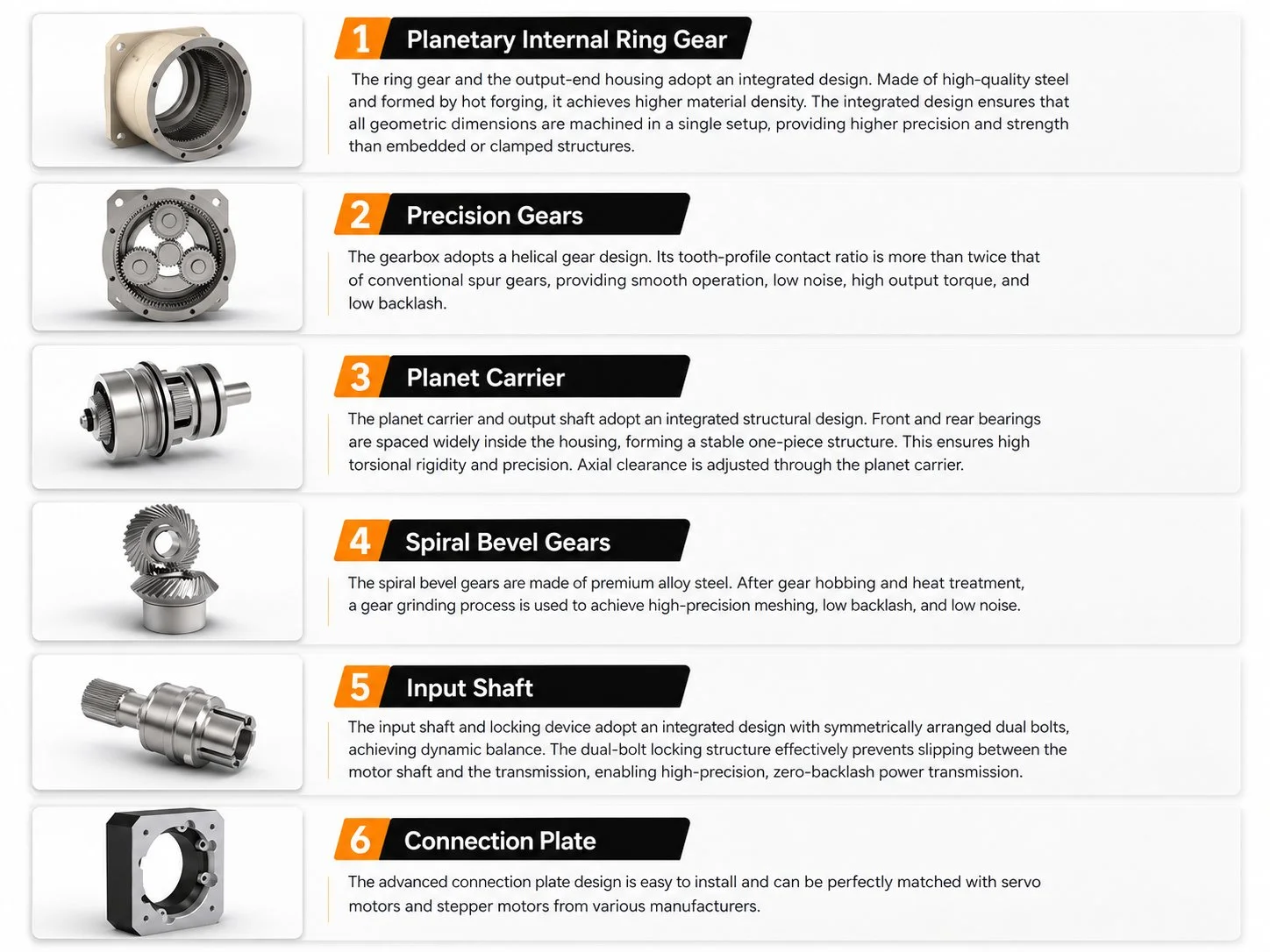
Εσωτερικά εξαρτήματα EP-TNR — Έξι στοιχεία σε ένα περίβλημα
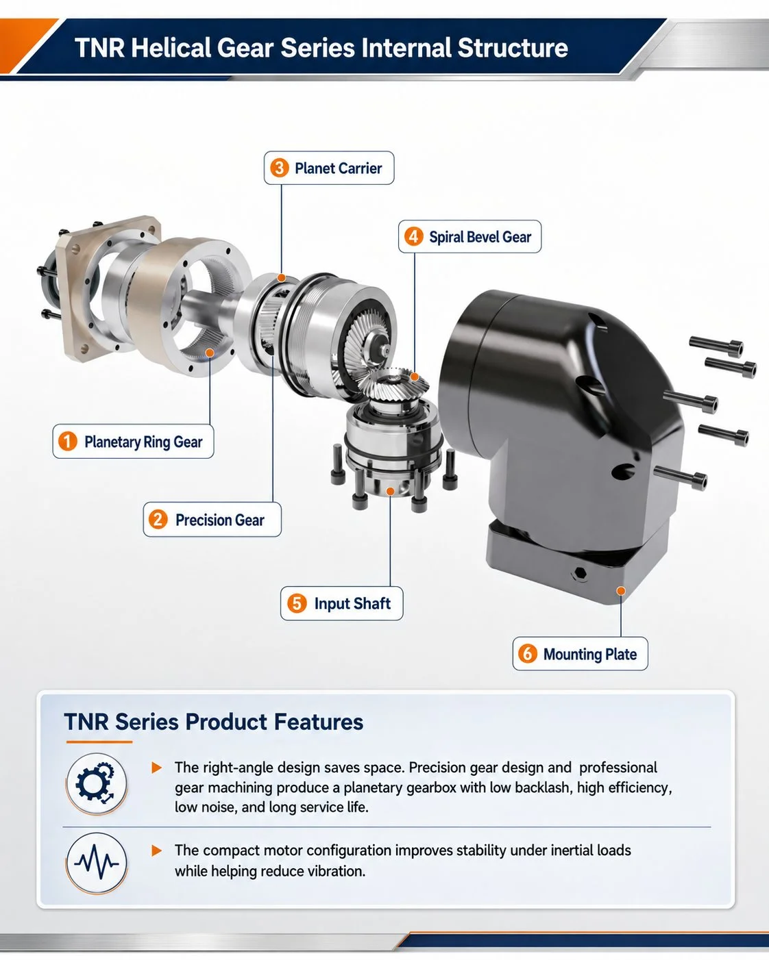
Το EP-TNR ενσωματώνει έξι υποσυστήματα ακριβείας σε μία μόνο σφραγισμένη μονάδα. Τα τρία πρώτα είναι κοινά με την οικογένεια εν σειρά EP-TNF. Τα στοιχεία τέσσερα έως έξι είναι ειδικά για τη διαμόρφωση ορθής γωνίας και διέπουν την απόδοση της κωνικής βαθμίδας που διακρίνει το EP-TNR τόσο από το EP-TNF όσο και από το EP-TMR με άξονα με κλειδί.
① Περίβλημα γραναζιού δακτυλίου — Σφυρήλατο μονοκόμματο
Κράμα χάλυβα, γρανάζι δακτυλίου και περίβλημα από ένα τσιμέντο. Όλες οι κρίσιμες οπές — εσωτερική διάμετρος γραναζωτού, έδρες ρουλεμάν εξόδου, οπή κωνικού γραναζιού — κατεργάζονται σε μία διάταξη, εξαλείφοντας τη συσσώρευση ομοκεντρικότητας από ξεχωριστά εξαρτήματα.
② Ελικοειδή Πλανητικά Γρανάζια
Ίδιο σετ ελικοειδών γραναζιών με τα EP-TNF και EP-TM. Λόγος επαφής >2,0, Κλάση DIN 5–6. Κατανέμει τη ροπή εξόδου σε τρεις ταυτόχρονες επαφές πλέγματος, παράγοντας ομαλότερη είσοδο στο κωνικό στάδιο από ό,τι θα έκανε ένα πλανητικό στάδιο με κωνικούς οδοντωτούς τροχούς.
③ Φορέας Πλανήτη + Άξονας Κωνικού Πινιόν
Ο φορέας και ο άξονας του κωνικού πινιόν κατεργάζονται ως ένα ενιαίο εξάρτημα. Η πλανητική έξοδος ρέει απευθείας στο κωνικό πινιόν χωρίς ενδιάμεση σύζευξη — δεν υπάρχει συσσωρευμένη εκκεντρότητα μεταξύ του άξονα του φορέα του πλανήτη και του άξονα του κωνικού πινιόν, η οποία είναι η κύρια πηγή θορύβου της κωνικής βαθμίδας σε συναρμολογημένα σχέδια.
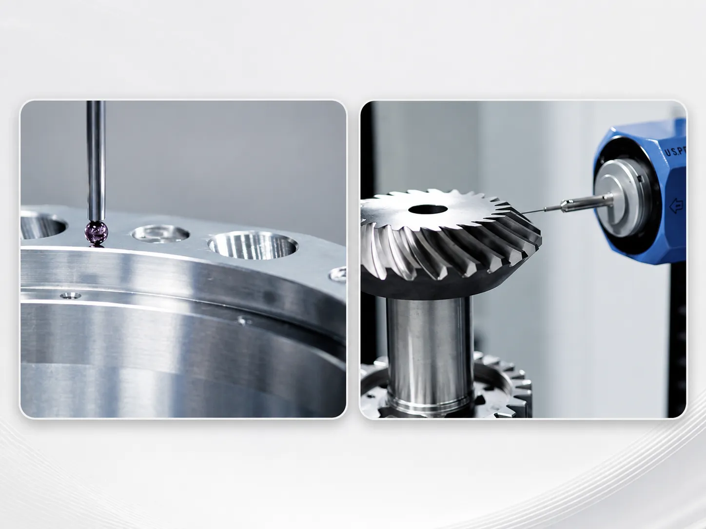
④ Ζεύγος σπειροειδών κωνικών γραναζιών — Αποκλειστικά EP-TNR
Χάλυβας υψηλής περιεκτικότητας σε κράμα, ενανθράκωση και σκλήρυνση σε 58–62 HRC, στη συνέχεια λείανση σε ειδικό λειαντήρα κωνικών γραναζιών. Γωνία έλικας 25–35°. Λόγος μετάδοσης 1:1 — η μείωση της ταχύτητας προέρχεται εξ ολοκλήρου από το πλανητικό στάδιο. το ζεύγος κωνικών αξόνων ανακατευθύνει μόνο την κατεύθυνση. Το προφορτωμένο ζεύγος ρουλεμάν γωνιακής επαφής στον άξονα εξόδου κωνικής αξόνων χειρίζεται τη συνδυασμένη δύναμη διαχωρισμού και το εφαρμοζόμενο ακτινικό φορτίο ως έναν ενιαίο υπολογισμό σχεδιασμού.
⑤ Άξονας εισόδου διπλής σφιγκτήρα
Δύο συμμετρικά αντίθετες βίδες σύσφιξης στην κάθετη οπή εισόδου. Μέγιστη ταχύτητα εισόδου 10.000 σ.α.λ. Συμβατό με οποιαδήποτε διάμετρο άξονα κινητήρα εντός του εύρους πλάκας προσαρμογέα. Η συμμετρική σύσφιξη αποτρέπει την παραμόρφωση του άξονα εισόδου που παράγουν τα σχέδια με μία βίδα κατά τη σύσφιξη.
⑥ Στρογγυλή φλάντζα εξόδου + πιλοτικό μητρώο
Επιφάνεια φλάντζας εξόδου και γείωση καταχωρητή πιλότου μετά τη συναρμολόγηση — ομοκεντρικότητα προς τον πραγματικό άξονα περιστροφής, όχι προς έναν ονομαστικό άξονα σχεδιασμού. Τυπική απόκλιση επιφάνειας φλάντζας ≤0,02 mm. Οι διαστάσεις του κύκλου του μπουλονιού και του καταχωρητή πιλότου ταιριάζουν με το EP-TNF στο ίδιο μέγεθος πλαισίου, επομένως οι διεπαφές μηχανής στην πλευρά εξόδου που έχουν σχεδιαστεί για EP-TNF μεταφέρονται στο EP-TNR χωρίς τροποποίηση.
Το TNR P1 ≤10 arcmin είναι η συνολική οπισθοδρόμηση της φλάντζας εξόδου — πλανητική τράπεζα συν κωνική τράπεζα μαζί, μετρημένη στη φλάντζα εξόδου σε προφόρτιση ±3% T₂ₙ. Κάθε EP-TNR αποστέλλεται με πιστοποιητικό μέτρησης εργοστασίου που δείχνει την πραγματική τιμή. Σε ακτίνα φλάντζας 100 mm, τα 10 arcmin αντιστοιχούν σε ≈0,29 mm κίνησης τόξου — αποδεκτό για όλους τους σερβοκινητήρες κλειστού βρόχου όπου ο κωδικοποιητής βρίσκεται στον άξονα του κινητήρα και για εφαρμογές ανοιχτού βρόχου όπου η ανοχή θέσης ≥0,3 mm.
Πώς να διαβάσετε έναν κωδικό μοντέλου EP-TNR
ελικοειδής στρογγυλή φλάντζα
060/090/115/142/180/220
L1: 3–20 · L2: 12–200
S1=στρογγυλό · S2=κλειδωμένο
P1≤10′ · P2≤12′
L=αριστερά · R=δεξιά · U=πάνω · D=κάτω
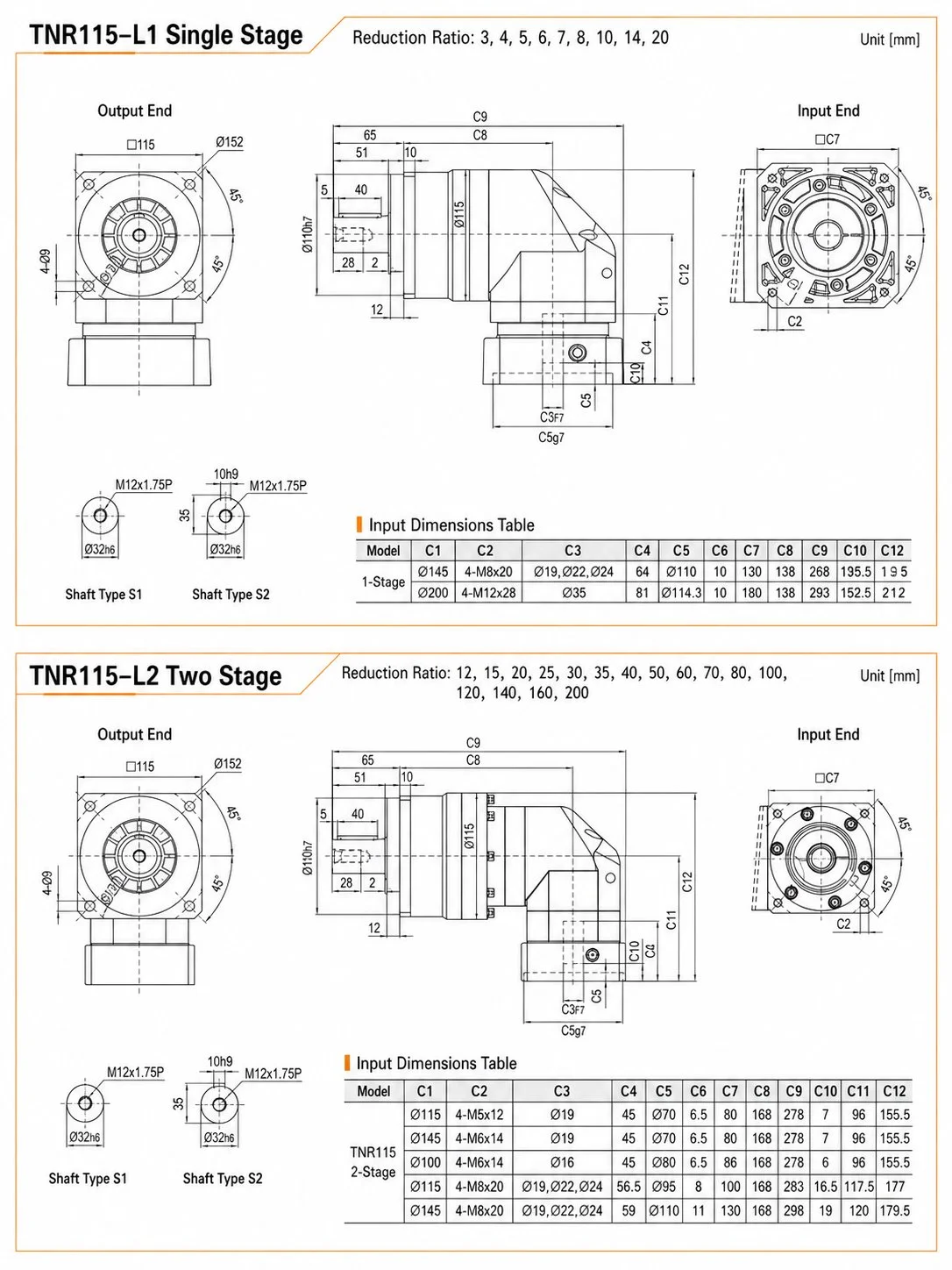
Διαστάσεις Φλάντζας Εισόδου Κινητήρα — TNR Μονοβάθμιο L1 (Κάθετη Πλευρά Εισόδου)
| Πλαίσιο | Φλάντζα εξόδου Ø | Πιλότος εισόδου Ø (C1) | Κύκλος / σπείρωμα μπουλονιού εισόδου (C2) | Άξονας εισόδου Ø (C3) | Αξονικό μήκος L1 C9 |
|---|---|---|---|---|---|
| TNR060 | Ø80 | Ø66.7 / Ø70 / Ø90 | 4-M4×10 / M5×12 / M6×14 | Ø8 / Ø11 / Ø19 | 153 χιλιοστά |
| TNR090 | Ø116 | Ø90 / Ø100 / Ø115 / Ø145 | 4-M5×12 – 4-M8×20 | Ø19 / Ø16 / Ø19,22 | 209 χιλιοστά |
| TNR115 | Ø152 | Ø145 / Ø200 | 4-M8×20 / 4-M12×28 | Ø19,22 / Ø35 | ~266 χιλιοστά |
| TNR142 | Ø186 | Ø145 / Ø200 | 4-M8×20 / 4-M12×28 | Ø22 / Ø35 | ~338 χιλιοστά |
| TNR180 | Ø240 | Ø200 (κατά παραγγελία) | 4-M12×28 | Ø42 / Ø55 | 405,5 χιλιοστά |
| TNR220 | Ø292 | Ø220 (κατά παραγγελία) | 4-M12×30 | Ø42 / Ø75 | 494,5 χιλιοστά |
Διαστάσεις εισόδου TNR180/220 με δυνατότητα διαμόρφωσης — προσδιορίστε τον κινητήρα κατά την παραγγελία. Επιβεβαιώστε όλες τις διαστάσεις με βάση το σχέδιο διαστάσεων της Korea Ever-Power. Το ύψος κάθετου L12 (συμπεριλαμβανομένης της φλάντζας εισόδου) είναι η κρίσιμη διάσταση για εγκαταστάσεις όπου ο κινητήρας εξέρχεται προς τα πάνω ή προς τα κάτω.
EP-TNR στην κορεατική βιομηχανία — Όπου η στρογγυλή φλάντζα έχει σημασία
① Κορεατικός 5-άξονας CNC άξονας Β — Στήλη περιορισμένου βάθους
Οι Κορεάτες κατασκευαστές συμπαγών κέντρων κατεργασίας 5 αξόνων αντιμετωπίζουν ένα αυστηρό όριο βάθους στήλης πίσω από την εμβέλεια του περιστροφικού τραπεζιού άξονα Β για το TNR090/115 στο i=25–50. Ο κινητήρας εξέρχεται πλευρικά εντός του πλάτους της στήλης. Η φλάντζα εξόδου μεγάλης διαμέτρου (Ø116 ή Ø152 mm) εδράζεται απευθείας στην οπή του περιβλήματος του τραπεζιού. Το αποτέλεσμα είναι ένα συγκρότημα άξονα Β 60–90 mm μικρότερο από το αντίστοιχο εν σειρά κινητήρα EP-TNF +, επιτρέποντας στενότερη διατομή στήλης και μετρήσιμη μείωση βάρους μηχανής σε μια παρτίδα παραγωγής.
② Κορεατική αρθρωτή άρθρωση καρπού Cobot — Άμεση τοποθέτηση ISO 9409
Κορεάτες συνεργατικοί κατασκευαστές ρομπότ που σχεδιάζουν co-bot 6 αξόνων για την αγορά της γενικής βιομηχανίας καθορίζουν το TNR060 στο i=16–20 για τον άξονα κύλισης του καρπού J4. Η φλάντζα εξόδου Ø80 mm ταιριάζει με τη διεπαφή φλάντζας ρομπότ μεγέθους 50 ISO 9409-1, επιτρέποντας στις τυπικές φλάντζες εργαλείου τελεστή να βιδώνονται απευθείας στην επιφάνεια εξόδου του κιβωτίου ταχυτήτων. Ο κινητήρας εξέρχεται κάθετα προς τον άξονα του αντιβραχίου, διατηρώντας την εξωτερική διάμετρο του αντιβραχίου στα 72–78 mm — κάτι που επιτυγχάνεται με το EP-TNR, κάτι που δεν είναι δυνατό με ένα ενσωματωμένο EP-TNF στο ίδιο επίπεδο ροπής.
③ Κορεατική Κεφαλή Δεικτών Ακριβείας — Άμεση Σύνδεση Χωρίς Δακτύλιο Προσαρμογέα
Οι Κορεάτες κατασκευαστές αξεσουάρ εργαλειομηχανών που κατασκευάζουν κεφαλές ευρετηρίου άμεσης κίνησης καθορίζουν το TNR090/115 στο i=20–40. Ο καταχωρητής πιλότου της φλάντζας εξόδου κεντράρει απευθείας τον άξονα της κεφαλής ευρετηρίου — χωρίς ενδιάμεσο δακτύλιο προσαρμογέα, χωρίς συσσωρευμένο σφάλμα ευθυγράμμισης από ανοχές κατεργασίας δακτυλίου. Για μηχανήματα συναρμολόγησης πολλαπλών σταθμών που λειτουργούν 24/7, η εξάλειψη ενός ενδιάμεσου εξαρτήματος ζεύξης εξαλείφει επίσης ένα στοιχείο λειτουργίας βλάβης από το πρόγραμμα συντήρησης. Η επιτεύξιμη ακρίβεια θέσης στην επιφάνεια του τραπεζιού ευρετηρίου εξαρτάται από την εκκεντρότητα της φλάντζας εξόδου EP-TNR (≤0,02 mm) συν την προφόρτιση του ρουλεμάν του άξονα της κεφαλής ευρετηρίου — συνήθως ≤0,05 mm συνολικά στο χείλος του τραπεζιού.
④ Πλευρική κίνηση κορεατικού φαρμακευτικού μεταφορέα — Ζώνη υγιεινής
Τα κορεατικά φαρμακευτικά συστήματα μεταφοράς κυψελών και υγρών απαιτούν μηχανισμούς κίνησης που τοποθετούνται στο ίδιο επίπεδο με το πλευρικό πλαίσιο του μεταφορέα — η ζώνη προϊόντος από πάνω πρέπει να είναι απαλλαγμένη από όλες τις μηχανικές προεξοχές. Το TNR060/090 με διαμόρφωση κινητήρα προς τα κάτω ή προς τα πάνω τοποθετείται στο ίδιο επίπεδο, η στρογγυλή φλάντζα κάθεται στην οπή της πλευρικής πλάκας του πλαισίου του μεταφορέα και ο κινητήρας πέφτει κάτω ή ανεβαίνει πάνω από την επάνω επιφάνεια του μεταφορέα. Η στεγανοποίηση IP65 χειρίζεται τον καθαρισμό πλύσης CIP. Η σφραγισμένη πλήρωση λίπους δεν παράγει σωματίδια — μια ρητή απαίτηση μεταφορέα καθαρού χώρου που αποκλείει τους ανοιχτούς μειωτήρες λουτρού λαδιού.
⑤ Κορεατικός ημιαγωγός EFEM — Ρομπότ Θήτα Άξονας
Οι μονάδες μπροστινού άκρου εξοπλισμού σε κορεατικά σετ εργαλείων fab χρησιμοποιούν TNR060 για τον άξονα θήτα (περιστροφής) του ρομπότ μεταφοράς πλακιδίων. Το συμπαγές περίβλημα — αξονικό βάθος 153 mm με τον κινητήρα να εξέρχεται πλευρικά — ταιριάζει στον περιορισμό αποτυπώματος εξοπλισμού EFEM που διέπει το βήμα του εργαλείου του διαδρόμου fab. Η στρογγυλή φλάντζα εξόδου κεντράρει τον πυργίσκο του ρομπότ απευθείας με εκκεντρότητα κάτω από 0,02 mm, συμβάλλοντας στην επαναληψιμότητα ευθυγράμμισης των εγκοπών πλακιδίων που απαιτείται από τα πρότυπα θύρας φόρτωσης SEMI E84 AMHS.
⑥ Γεωργικός Εξοπλισμός — Περιστροφή ακριβείας του φορείου σποράς
Οι σύγχρονες σπαρτικές μηχανές ακριβείας με καθοδήγηση GPS χρησιμοποιούν σερβοκινούμενα βαγονέτα μονάδων σειράς με σερβοέλεγχο που περιστρέφονται για να ακολουθούν τα περιγράμματα του χωραφιού και τις στροφές του κεφαλαριού. Το TNR090 σε i=25–50 τοποθετεί τον κινητήρα κατά μήκος του πλαισίου του βαγονιού, ενώ παράλληλα παρέχει ροπή φλάντζας εξόδου απευθείας στο ρουλεμάν περιστροφής του βαγονιού. Τα κιβώτια ταχυτήτων πολλαπλών εξόδων κατάντη γεωργικής παραγωγής κατανέμουν στη συνέχεια την ισχύ στις μεμονωμένες μονάδες σειράς από την μία έξοδο TNR, διατηρώντας τον αριθμό των σερβοκινητήρων ελάχιστο και το σύστημα ελέγχου απλό. Η στεγανοποίηση IP65 και το εύρος θερμοκρασίας από -10°C έως +90°C καλύπτουν όλες τις εποχιακές συνθήκες λειτουργίας στο χωράφι.
Γιατί οι μηχανικοί προδιαγράφουν το Korea Ever-Power EP-TNR
📐
Διεπαφή πλευράς εξόδου Ίδια με το EP-TNF
Η διάμετρος της φλάντζας εξόδου EP-TNR, ο κύκλος του κοχλία, ο καταχωρητής πιλότου και η ανοχή του άξονα είναι πανομοιότυπα με το EP-TNF στο ίδιο μέγεθος πλαισίου. Μια διεπαφή μηχανής σχεδιασμένη για EP-TNF μεταφέρεται στο EP-TNR χωρίς καμία τροποποίηση στην πλευρά εξόδου — αλλάζει μόνο η διάταξη στήριξης του κινητήρα. Αυτό σημαίνει ότι οι μηχανικοί μπορούν να επανασχεδιάσουν την πλευρά του κινητήρα για να εξοικονομήσουν αξονικό βάθος χωρίς να επανασχεδιάσουν ολόκληρο το συγκρότημα άξονα.
🔒
Στάδιο λοξοτμήσεων καλυμμένο με σφράγιση εφ' όρου ζωής — Χωρίς ξεχωριστή συντήρηση
Πολλά κιβώτια ταχυτήτων ορθής γωνίας με κωνικό στάδιο χρησιμοποιούν ξεχωριστή δεξαμενή λαδιού για τα κωνικά γρανάζια, η οποία απαιτεί περιοδικούς ελέγχους και αλλαγές στάθμης λαδιού. Το EP-TNR χρησιμοποιεί ένα μόνο γράσο εργοστασιακής σφραγίδας που καλύπτει τόσο το ελικοειδές πλανητικό στάδιο όσο και το σπειροειδές κωνικό στάδιο στο ίδιο περίβλημα — χωρίς θύρα πρόσβασης, χωρίς μετρητή στάθμης λαδιού, χωρίς πρόγραμμα λίπανσης ειδικά για τη κωνικό τμήμα κατά τη διάρκεια ολόκληρης της διάρκειας ζωής των 20.000 ωρών.
📋
Πιστοποιητικό Συνολικής Αντίδρασης — Μετρήθηκε με Φλάντζα, Δεν Εκτιμήθηκε
Η τιμή της οπισθοδρόμησης στο πιστοποιητικό παράδοσης EP-TNR μετριέται στη φλάντζα εξόδου — το συνδυασμένο σύνολο των συνεισφορών της πλανητικής τράπεζας και της κωνικής τράπεζας — χρησιμοποιώντας την ίδια μέθοδο δοκιμής προφόρτισης ±3% T₂ₙ όπως η EP-TM και η EP-TNF. Δεν πρόκειται για ένα εκτιμώμενο άθροισμα δύο ξεχωριστών μετρήσεων τράπεζας. Οι μηχανικοί λαμβάνουν την πραγματική τιμή για τη συγκεκριμένη μονάδα τους, την οποία μπορούν να συγκρίνουν με τις προδιαγραφές ποιότητας και να χρησιμοποιήσουν ως βάση εγκατάστασης για ετήσιους ελέγχους συντήρησης.
🎯
Υπολογισμός Αξονικής Εξοικονόμησης χωρίς Χρέωση — Πριν από την Παραγγελία
Η Korea Ever-Power παρέχει μια δωρεάν σύγκριση φακέλων εγκατάστασης — αξονικό βάθος EP-TNR έναντι EP-TNF + τον συγκεκριμένο κινητήρα σας — πριν από την υποβολή της παραγγελίας. Παρέχετε τον αριθμό μοντέλου του κινητήρα και το διαθέσιμο βάθος μηχανής πίσω από τη φλάντζα εξόδου. Η απάντηση περιλαμβάνει την ακριβή αξονική εξοικονόμηση σε χιλιοστά, το κάθετο ύψος L12 με τον κινητήρα στην επιλεγμένη κατεύθυνση και ένα σχέδιο διαστάσεων για το συγκεκριμένο πλαίσιο και αναλογία. Απόκριση την ίδια ημέρα στα Αγγλικά.
⚡
Εύρος αναλογίας προς i=200 — Εξαιρετικά αργές ταχύτητες εξόδου
Το διβάθμιο EP-TNR φτάνει το i=200, μεγαλύτερο εύρος από το διβάθμιο εύρος του EP-TNF. Ένα TNR090 στα i=200 από έναν κινητήρα 3.000 rpm παράγει ισχύ 15 rpm — κατάλληλο για κινήσεις κεφαλής βαρέος μεταφορικού ιμάντα, κινήσεις κοχλιοφόρων μεταφορικών ιμάντων και κινήσεις δακτυλίων αργής περιστροφής, όπου απαιτείται συμπαγές αξονικό βάθος και το ενσωματωμένο EP-TNF θα απαιτούσε ξεχωριστό εξωτερικό στάδιο μείωσης για να φτάσει σε ισοδύναμη ταχύτητα.
🌡️
−10°C έως +90°C — Ίδιο εύρος με το EP-TNF
Το στάδιο της λοξοτομής δεν εισάγει κανέναν περιορισμό στο εύρος θερμοκρασίας λειτουργίας. Οι εφαρμογές που χρησιμοποιούν EP-TNF σε περιβάλλοντα ψυχρής αλυσίδας εφοδιαστικής αλυσίδας στην Κορέα ή σε περιβάλλοντα θερμής επεξεργασίας τροφίμων στην Κορέα μπορούν να αντικαταστήσουν το EP-TNR χωρίς καμία λίπανση ή τροποποίηση στεγανοποίησης. Η προδιαγραφή σφραγισμένου γράσου καλύπτει και τα δύο στάδια σε όλο το ονομαστικό εύρος θερμοκρασίας χωρίς αλλαγή.
Κριτικές πελατών και σχόλια για εφαρμογές
5 ★
87%
4 ★
11%
≤3 ★
2%
TNR115 i=40 διπλού σταδίου για τον άξονα Β του νέου μας συμπαγούς 5αξονικού VMC. Η προηγούμενη γενιά μηχανημάτων χρησιμοποιούσε ένα EP-TNF115 με τον κινητήρα Yaskawa σε σειρά — η συνολική συναρμολόγηση ήταν 337 mm, γεγονός που μας ώθησε σε μια ευρύτερη στήλη από ό,τι θέλαμε. Με το EP-TNR115 το αξονικό βάθος είναι 266 mm και ο κινητήρας εξέρχεται αριστερά μέσα στη στήλη. Η διατομή της στήλης μειώθηκε κατά 65 mm, εξοικονομώντας 9 kg ανά μηχανή. Η Korea Ever-Power έστειλε το πλήρες σχέδιο διαστάσεων και επιβεβαίωσε την φλάντζα εισόδου για τον κινητήρα Yaskawa SGMGV-09A εντός 4 ωρών από το ερώτημά μου.
EP-TNR060 i=16 δύο σταδίων για την άρθρωση κύλισης καρπού J4. Η στοχευόμενη εξωτερική διάμετρος του αντιβραχίου ήταν 76 mm — με ένα τυπικό κιβώτιο ταχυτήτων σε σειρά με αυτή τη ροπή στρέψης, το αντιβράχιο θα είχε διάμετρο τουλάχιστον 95 mm. Το EP-TNR060 (σώμα φλάντζας Ø80 mm) μας επέτρεψε να επιτύχουμε εξωτερική διάμετρο αντιβραχίου 74 mm. Η αντιστοίχιση φλάντζας ISO 9409-1 σήμαινε ότι οι τυπικοί προσαρμογείς γρήγορης αλλαγής εργαλείων μας ταιριάζουν χωρίς καμία τροποποίηση. Η οπισθοδρόμηση P2 ≤10 σε λεπτά τόξου είναι πλήρως εντός των ανοχών για τον έλεγχο θέσης καρπού κλειστού βρόχου. 22 μονάδες αναπτύχθηκαν σε δύο μοντέλα cobot — χωρίς προβλήματα πεδίου σε 11 μήνες.
Μονοβάθμια διαμόρφωση EP-TNR090 i=20, με κινητήρα προς τα κάτω, για κινήσεις κεφαλής μεταφορικού ιμάντα blister στην εγκατάσταση παραγωγής μας που συμμορφώνεται με το KFDA. Ο προηγούμενος μειωτήρας ατέρμονα κοχλία σε αυτήν τη θέση απαιτούσε τριμηνιαίες αλλαγές λαδιού — μια διαδικασία 40 λεπτών ανά κεφαλή μεταφορικού ιμάντα που συσσωρεύτηκε σε σημαντικές ώρες συντήρησης σε μια εγκατάσταση 24 γραμμών. Το σφραγισμένο γράσο EP-TNR εξάλειψε εντελώς το πρόγραμμα αλλαγής λαδιού. Το IP65 χειρίζεται την καθημερινή πλύση αφρού CIP. Μετά από 14 μήνες λειτουργίας και τρεις προγραμματισμένους ελέγχους, και οι 28 μονάδες παραμένουν εντός της τιμής οπισθοδρόμησης του πιστοποιητικού παράδοσης.
Μοιραστείτε την εμπειρία σας με την εφαρμογή EP-TNR. Επικοινωνήστε με την Korea Ever-Power: [email protected]
Ενσωμάτωση συστήματος μετάδοσης κίνησης — Συμπληρωματικά προϊόντα
Μειωτήρες ατέρμονα κοχλία — Αυτοασφαλιζόμενο δεύτερο στάδιο
Για κατακόρυφες στήλες συγκράτησης φορτίου και άξονες ανύψωσης χωρίς αντιστάθμιση όπου ο μηχανισμός κίνησης πρέπει να διατηρεί τη θέση του υπό απώλεια ισχύος, συνδυάζοντας το EP-TNR με ένα κατάντη σύστημα μειωτήρας ατέρμονα κοχλία Παρέχει τόσο την εξοικονόμηση αξονικού βάθους όσο και την ικανότητα αυτοασφαλίσματος. Ένα TNR090 στο i=20 (η≥95%) σε συνδυασμό με έναν κοχλία στο i=50 (η≈60%) παράγει συνδυασμένο i=1.000 με αυτοασφαλιζόμενο, συνολικό η≈57%. Η έξοδος ορθής γωνίας του EP-TNR απλοποιεί επίσης τη μηχανική διάταξη όταν ο άξονας του μειωτήρα κοχλία πρέπει να είναι κάθετος στον άξονα του κινητήρα — το EP-TNR εκτελεί τόσο την περιστροφή 90° όσο και την πρωτεύουσα μείωση σε ένα περίβλημα.
Γεωργικά κιβώτια ταχυτήτων — Εξοπλισμός ακριβείας πεδίου
Σε εξοπλισμό ακριβείας γεωργίας όπου ο σερβοκινητήρας πρέπει να βρίσκεται κατά μήκος του πλαισίου του μηχανήματος και τα στοιχεία εργασίας λειτουργούν κάθετα προς την κατεύθυνση κίνησης, η έξοδος φλάντζας ορθής γωνίας του EP-TNR τροφοδοτεί απευθείας την κατάντη ροή. γεωργικά κιβώτια ταχυτήτων πολλαπλών εξόδωνΗ στρογγυλή φλάντζα εξόδου επιτρέπει άμεση δομική σύνδεση με τη φλάντζα εισόδου του γεωργικού κιβωτίου ταχυτήτων — χωρίς άξονα, χωρίς σύνδεσμο, χωρίς ρύθμιση ευθυγράμμισης στο χωράφι. Το EP-TNR180/220 σε i=50–100 καλύπτει το εύρος 600–1.200 N·m που είναι τυπικό για τους κύριους άξονες κίνησης της κεφαλής θεριζοαλωνιστικής μηχανής και της σπαρτικής μηχανής ακριβείας.
Σχετικά προϊόντα — Η οικογένεια ορθογώνιων και φλαντζών
EP-TNF — Στρογγυλή φλάντζα, εν σειρά
Ίδια στρογγυλή επιφάνεια εξόδου φλάντζας με το EP-TNR. Ομοαξονικός κινητήρας πίσω από την έξοδο. Χαμηλότερη οπισθοδρόμηση (P1 ≤5 λεπτά τόξου) επειδή δεν υπάρχει κωνικό στάδιο. Επιλέξτε EP-TNF όταν το αξονικό βάθος επιτρέπει την εν σειρά τοποθέτηση του κινητήρα και η ελάχιστη οπισθοδρόμηση είναι η προτεραιότητα.
EP-TMR — Ορθογώνιος, Κλειδωμένος Άξονας
Ορθή γωνία 90°, ίδια ευελιξία κατεύθυνσης κινητήρα με το EP-TNR, αλλά έξοδος μέσω στρογγυλού/κλειδωμένου άξονα αντί για φλάντζα με μπουλόνι. Επιλέξτε το EP-TMR για εφαρμογές οδοντωτής ράγας και γραναζιού, σφαιρικής βίδας συνδεδεμένης με σύνδεσμο ή άξονα τροχαλίας μεταφορικού ιμάντα.
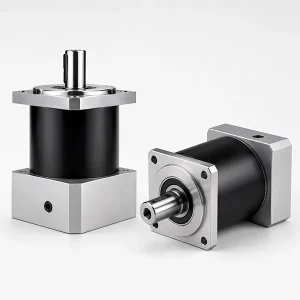
EP-TM — Ενσωματωμένος άξονας με κλειδί
Υψηλότερη απόδοση (≥97% L1), χαμηλότερη οπισθοδρόμηση (P0 ≤1 λεπτό τόξου), χωρίς κωνικό στάδιο. Ο βασικός ελικοειδής πλανητικός κινητήρας για όλες τις εφαρμογές όπου το αξονικό βάθος δεν περιορίζεται και είναι δυνατή η τοποθέτηση του κινητήρα σε σειρά.
EP-TEG — Υπερ-Ακρίβεια P0
P0 ≤1 έξοδος φλάντζας σε σειρά σε λεπτά τόξου. Για εξοπλισμό ημιαγωγών, οπτικά ακριβείας και περιστροφικά τραπέζια CNC εξαιρετικά ακριβείας όπου η οπισθοδρόμηση EP-TNR υπερβαίνει τον προϋπολογισμό σφάλματος συστήματος.
Συχνές ερωτήσεις — Σειρά EP-TNR
Καθορίστε το EP-TNR σας — Περιλαμβάνεται δωρεάν υπολογισμός αξονικής εξοικονόμησης
Παρέχετε το μοντέλο του κινητήρα σας, την απαιτούμενη σχέση, το διαθέσιμο αξονικό βάθος και την προτιμώμενη κατεύθυνση εξόδου του κινητήρα — Το Korea Ever-Power επιστρέφει την ακριβή αξονική εξοικονόμηση έναντι της ενσωματωμένης διαμόρφωσης, το κάθετο ύψος L12, ένα σχέδιο διαστάσεων και μια επιβεβαίωση διαθεσιμότητας αποθέματος. Απάντηση την ίδια ημέρα.
Διαμόρφωση φλάντζας ορθής γωνίας · Πλαίσια σε απόθεμα 060–142 · Παράδοση την ίδια εβδομάδα σε τυπικές διαμορφώσεις
Επιπλέον πληροφορίες
| Συντάκτης | Cxm |
|---|
Σχετικά προϊόντα
-
Πλανητικό κιβώτιο ταχυτήτων υψηλής ακρίβειας με τετραγωνική φλάντζα σειράς EP-AB (EP-AB042 έως EP-AB220)
-
Πλανητικό κιβώτιο ταχυτήτων εξοικονόμησης ενέργειας σειράς EP-BPG — Τυπική βιομηχανική μετάδοση κίνησης (EP-BPG040 έως EP-BPG160)
-
Πλανητικό κιβώτιο ταχυτήτων υψηλής ακρίβειας σειράς EP-BAF — Άξονας εξόδου υψηλής ακαμψίας (EP-BAF042 έως EP-BAF220)
-
Πλανητικό κιβώτιο ταχυτήτων υψηλής ακρίβειας σειράς BAE — Τύπος μεγάλης φλάντζας (EP-BAE050 έως EP-BAE235)
-
Πλανητικό κιβώτιο ταχυτήτων υψηλής ακρίβειας ορθής γωνίας σειράς BADR — Στρογγυλή φλάντζα (EP-BADR047 έως EP-BADR255)
-
Πλανητικό κιβώτιο ταχυτήτων υψηλής ακρίβειας σειράς BAB — Τυπική φλάντζα (EP-BAB042 έως EP-BAB220)
-
Πλανητικό κιβώτιο ταχυτήτων υψηλής ακρίβειας για σερβοκινητήρες — Σειρά PLE/PLF
-
Πλανητικό κιβώτιο ταχυτήτων PLS Precision για βιομηχανικούς κινητήρες αλυσίδας


